A Little History
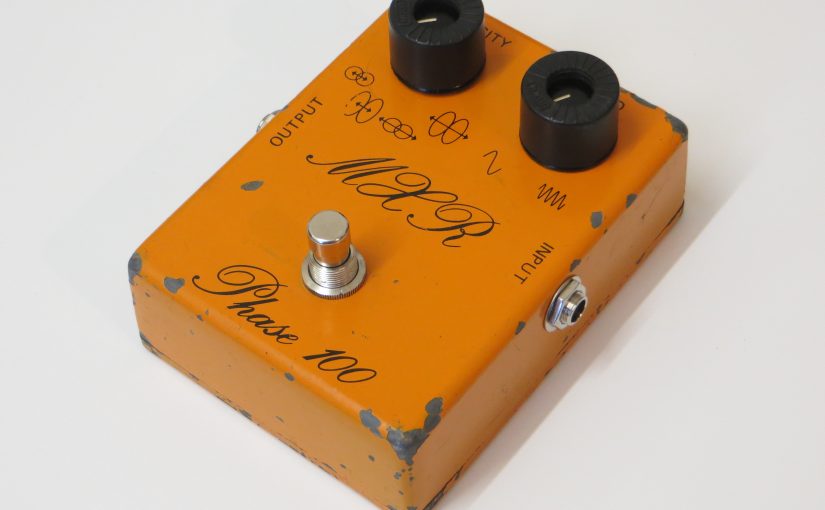
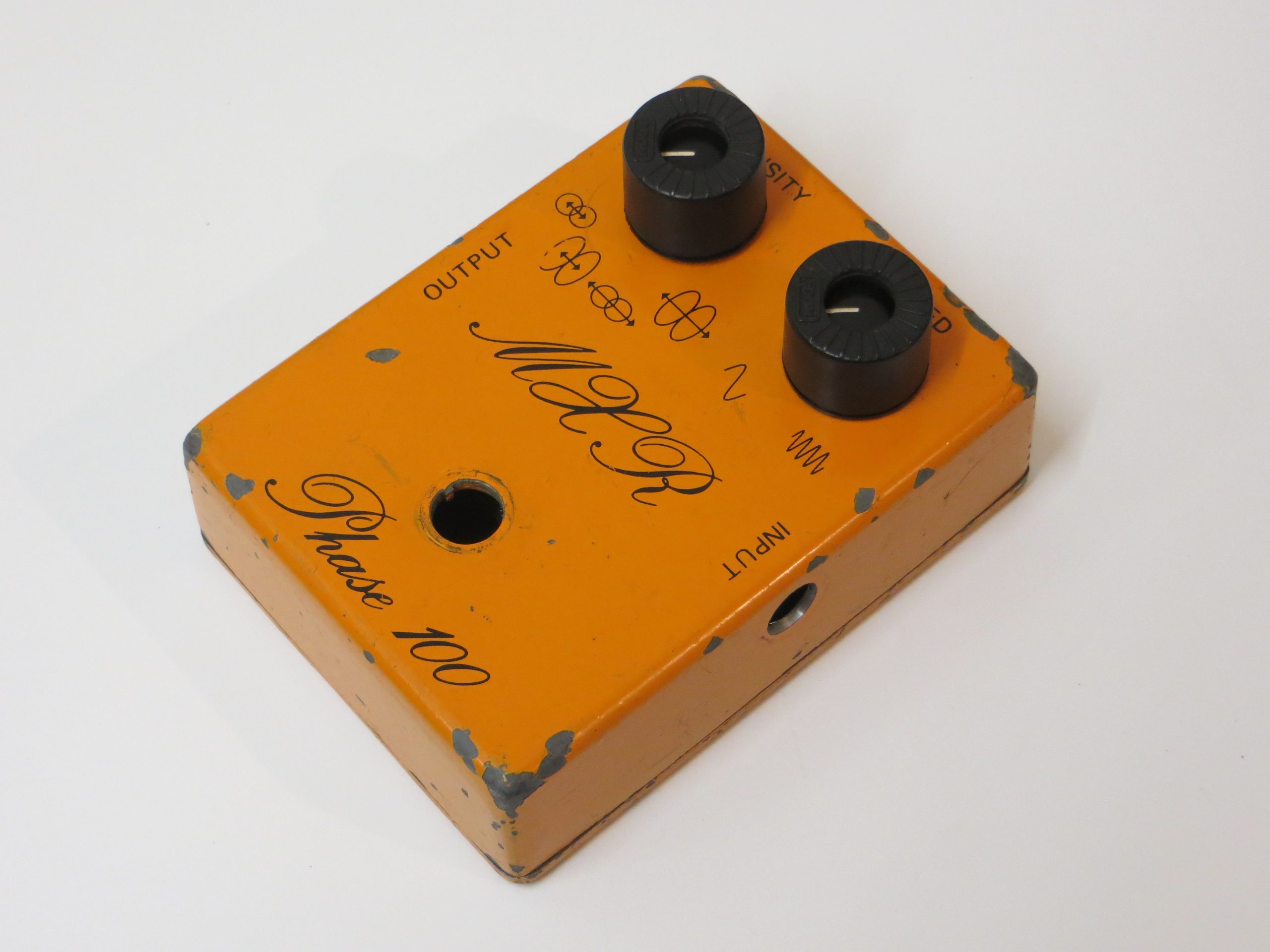
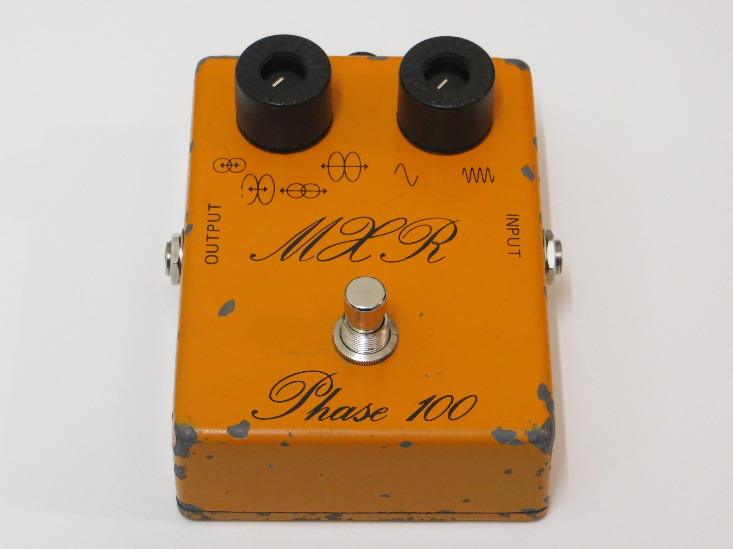
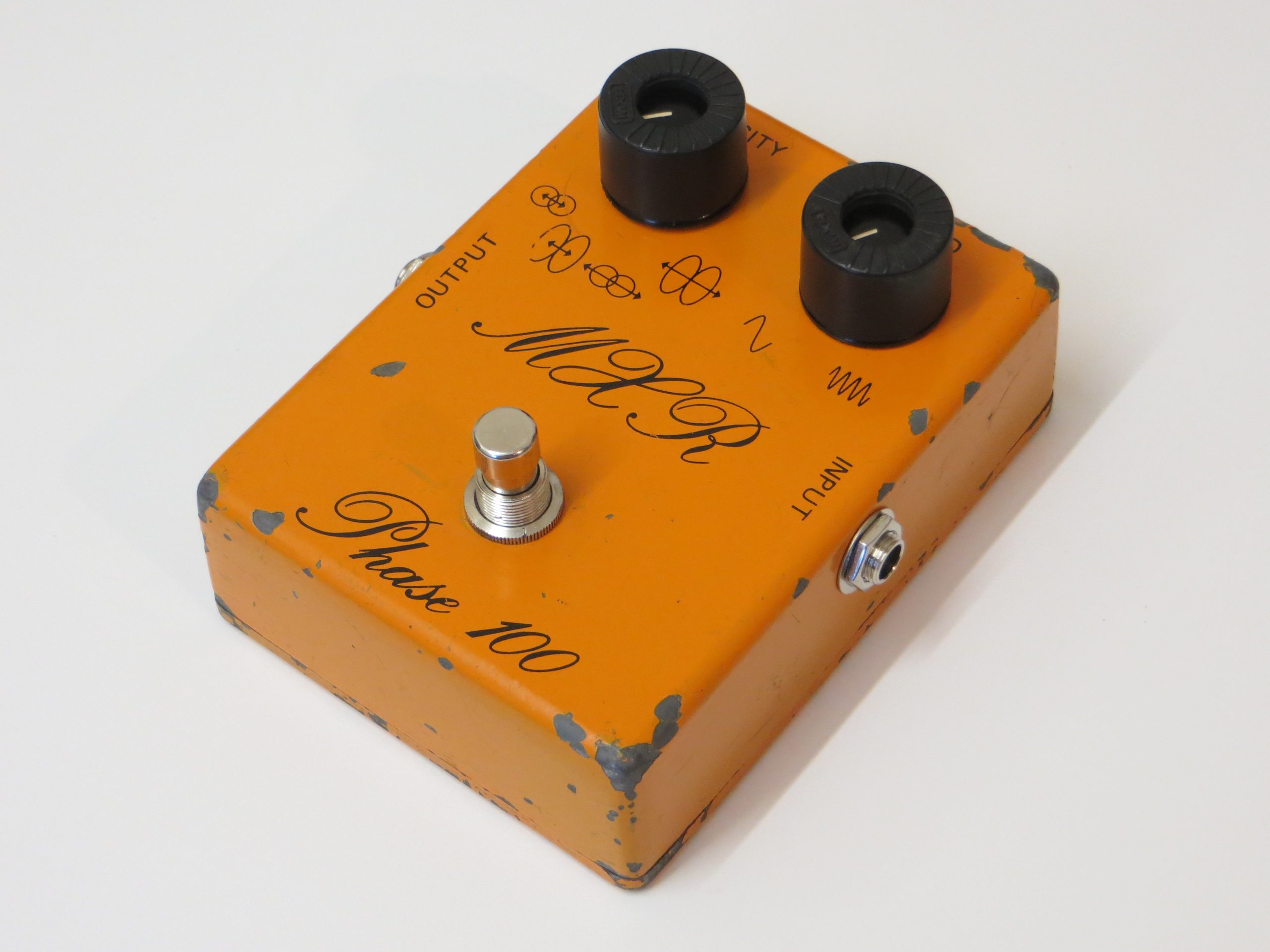
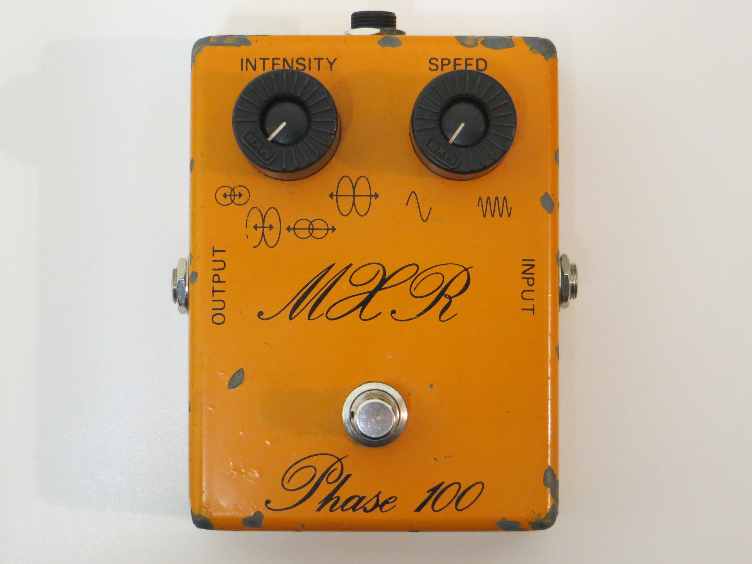
I bought this vintage MXR Phase 100 from a little second hand music shop in Bradford. I believe the year was 1998. At this time MXR pedals were relatively unwanted and had mostly been forgotten, at least that’s the impression I got since this pedal had sat in the window of this music shop for weeks along with a vintage MXR Flanger and vintage Stereo Chorus. I think I paid £35 or £40 for this particular Phase 100.
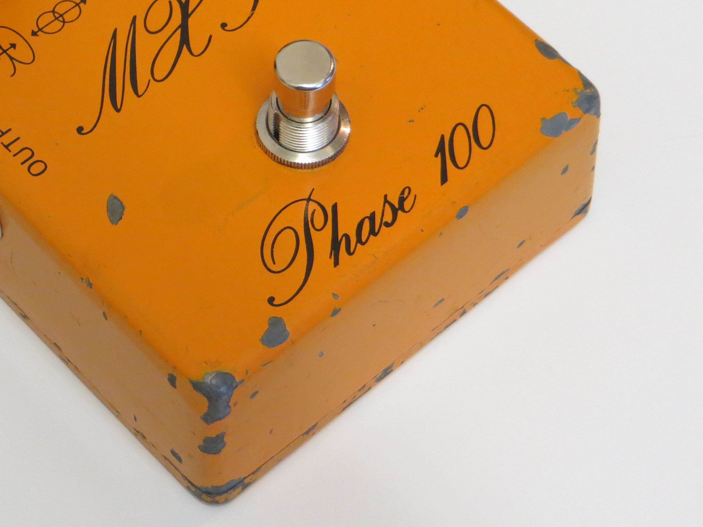
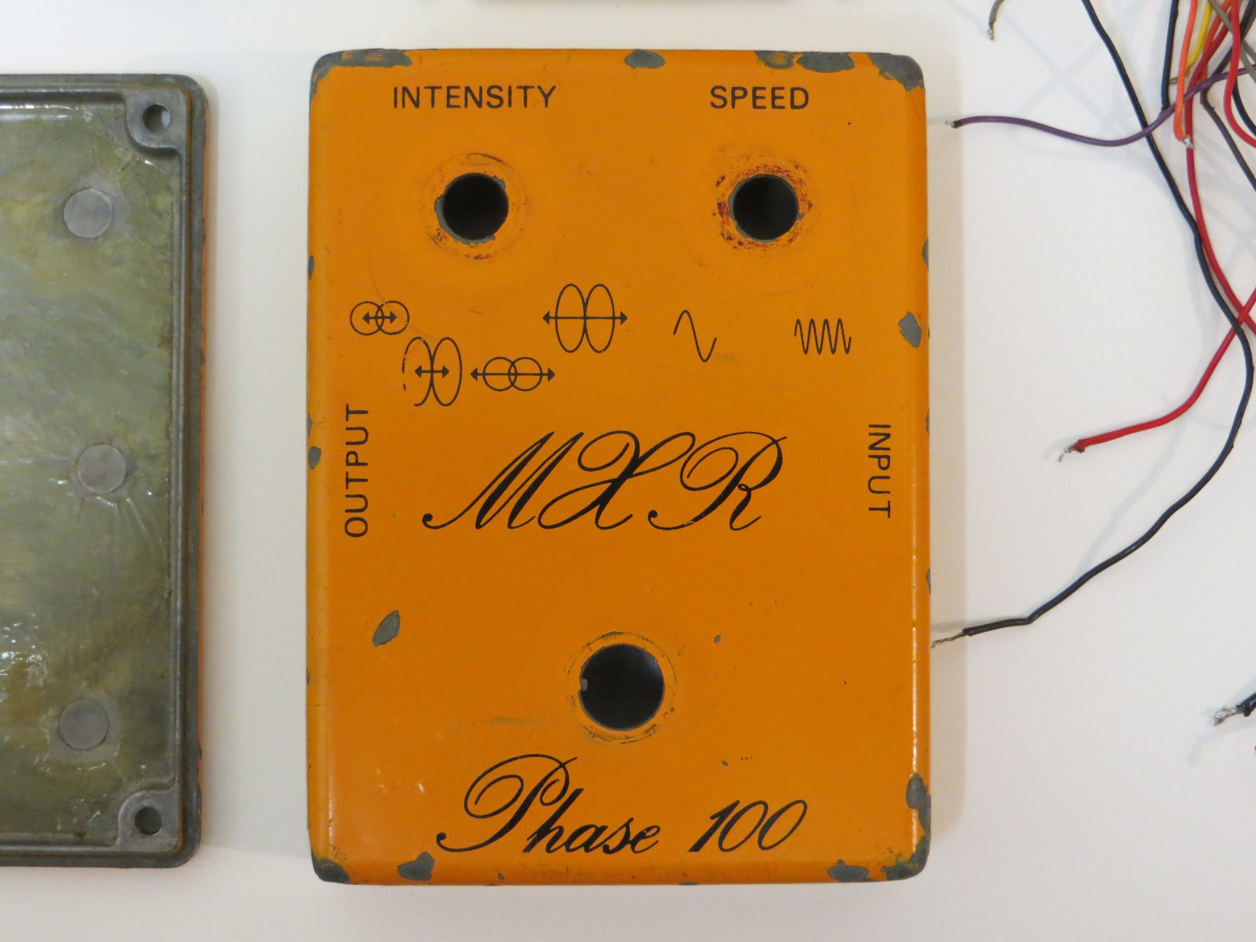
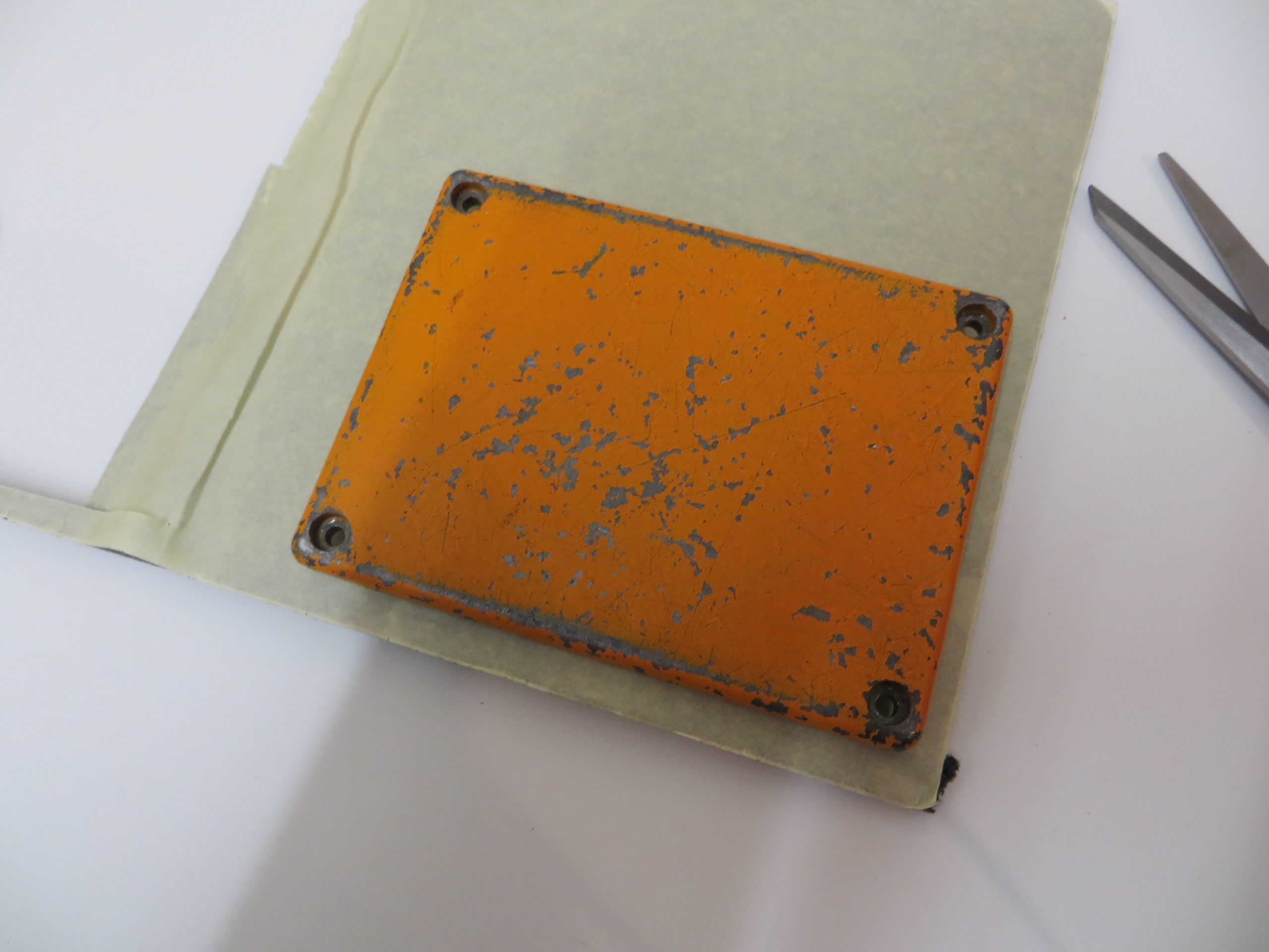
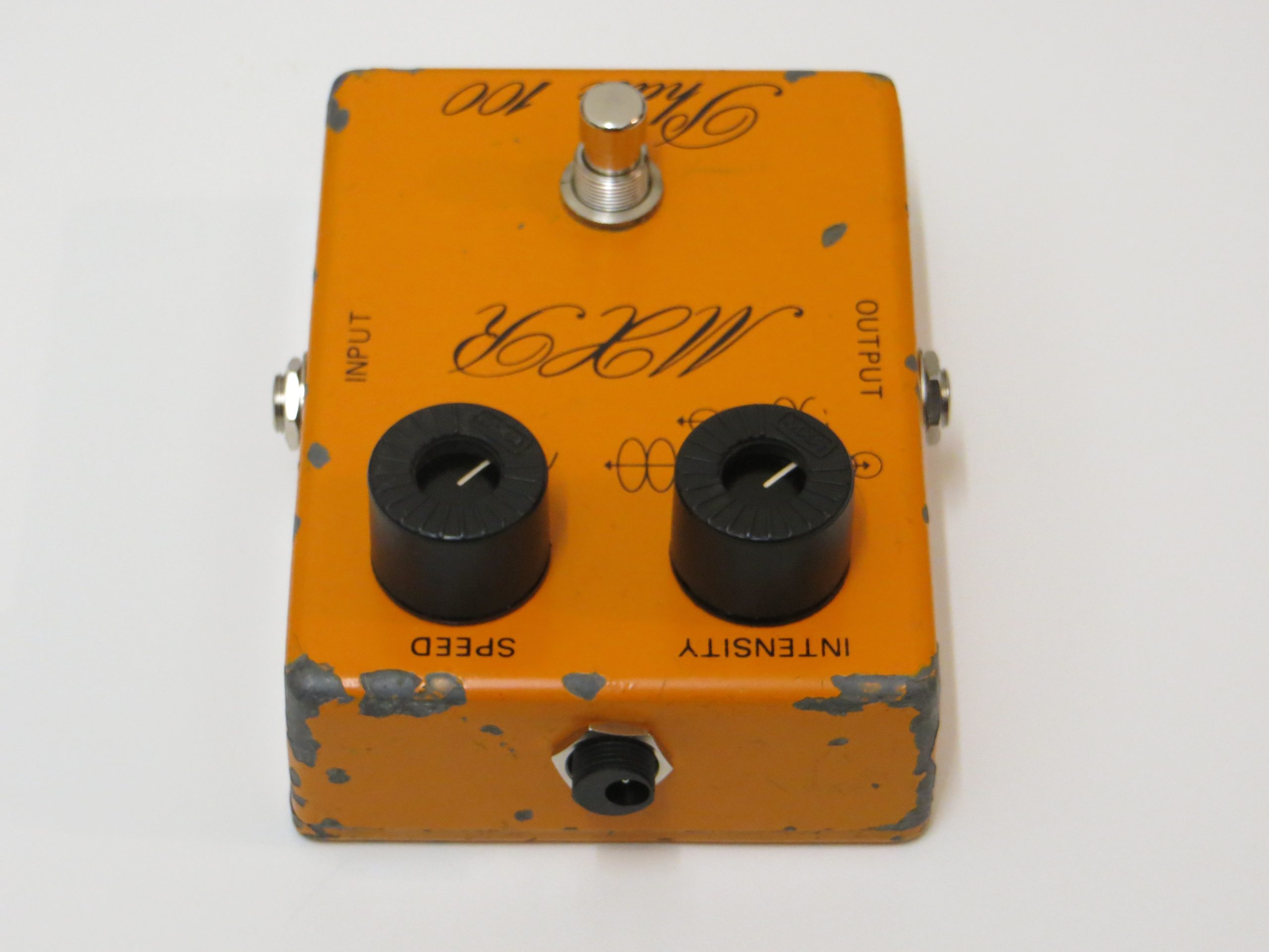
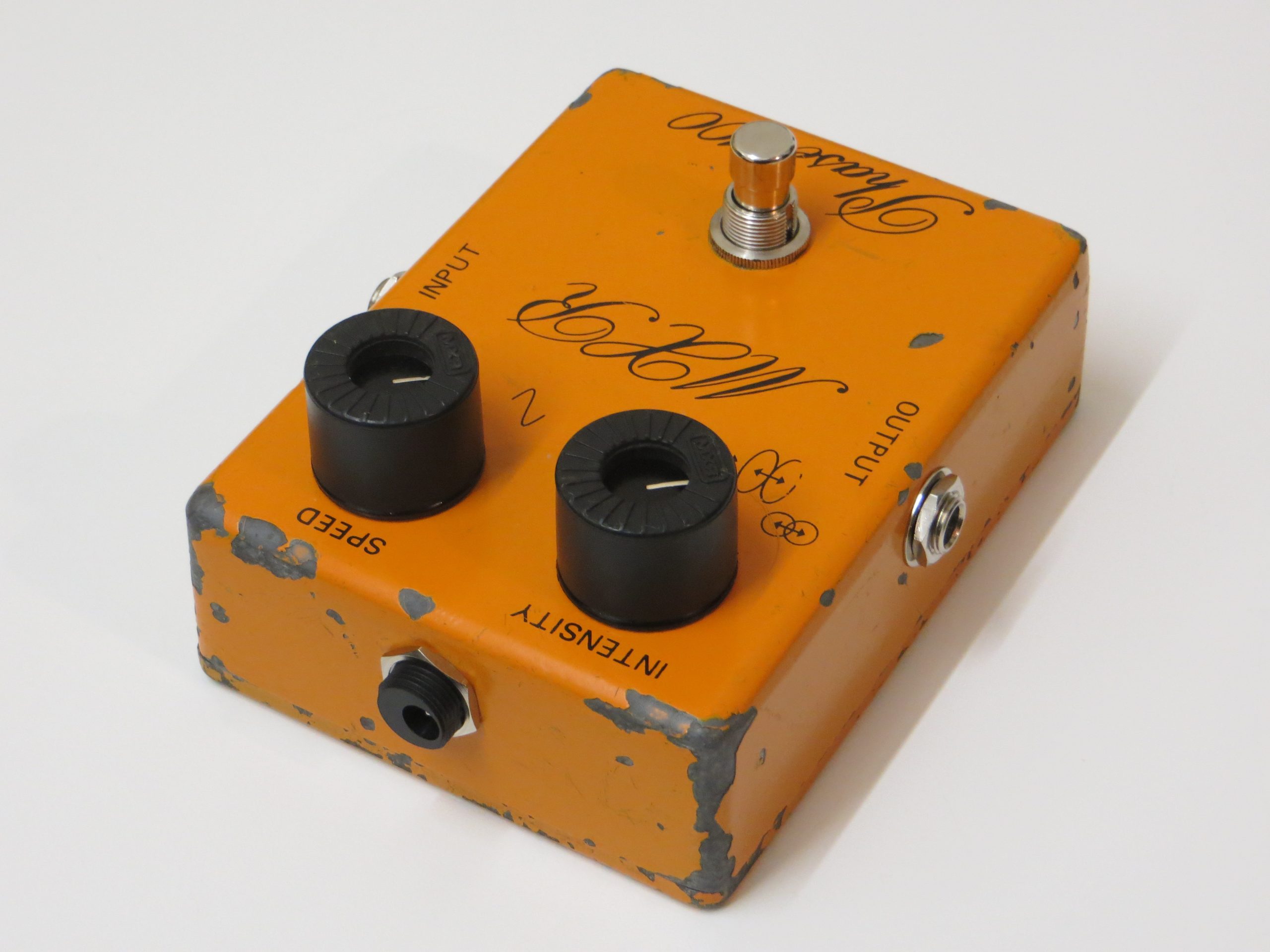
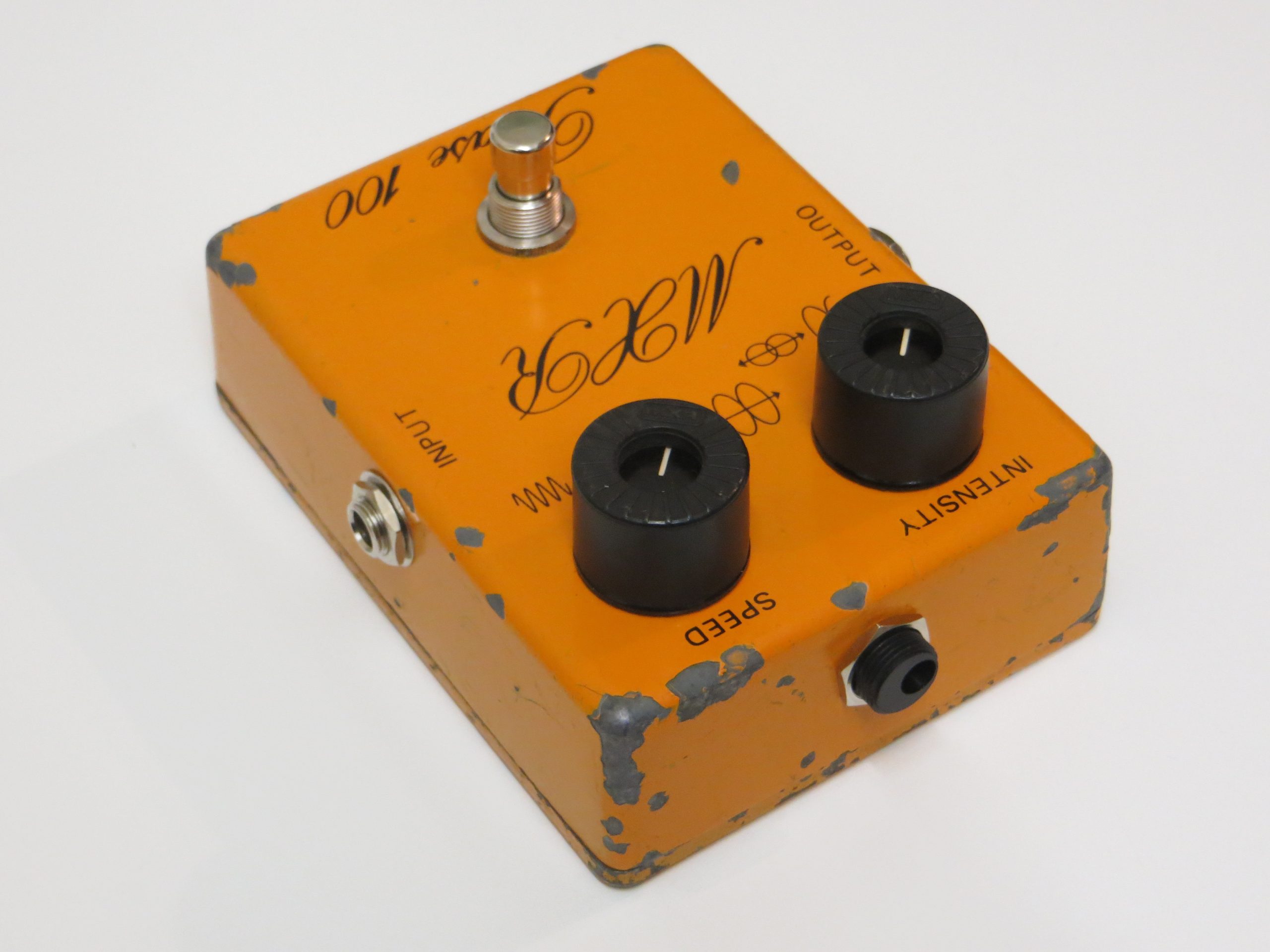
As you can see the pedal looks to have been through quite a life. Who knows what stages this thing sat on or who owned it originally.
The pedal was used on a number of songs in my then band Sand. The songs ‘E’, named so because it was in the key of E, and ‘The Todwell Lion’. A few years later my band broke up and I became a bass player. The pedal was then relegated to bedroom use.
At this time I was electronics curious and always opened up pedals or other equipment to just look at the insides. I had no idea how things worked or how to solder or anything like that, I just enjoyed looking at them.
The insides of this pedal were not in good condition. Rust, muck, and wires hanging on by threads. The cable jacks were also wobbly and not holding the guitar cables very well. The process of my meddling had also broken a few of the delicate wires. So I needed to find someone to do a complete rewire of the pedal, install a true bypass switch, and fix the jack sockets.
Around the year 2000/2001 I was given the details of a repair technician that had done some work on a friend’s amp so I took the pedal to him. After discussing the pedal briefly, he told me the pedal was already true-bypass. This should have been a red flag for me but I trusted him so left the pedal for him to do the other work. Fix the wiring and replace the jack sockets.
The pedal worked for a little while after this but once again it stopped working. I opened the pedal up and saw that more of the rusty, brittle wires had snapped inside. Even at that time with no knowledge of electronics I could tell that the work done was poor and the wire fixes were simply quick fixes to get the pedal working again. It was not professional work. I believe this cost me about £40, not cheap in 2000. So the pedal was shelved and not touched again.
If you want something doing well, do it yourself.
Now roughly 20 years later I am in possession of some electronics knowledge and some fine soldering skills so it was time to bring this pedal back to life and do the work I had always wanted doing.
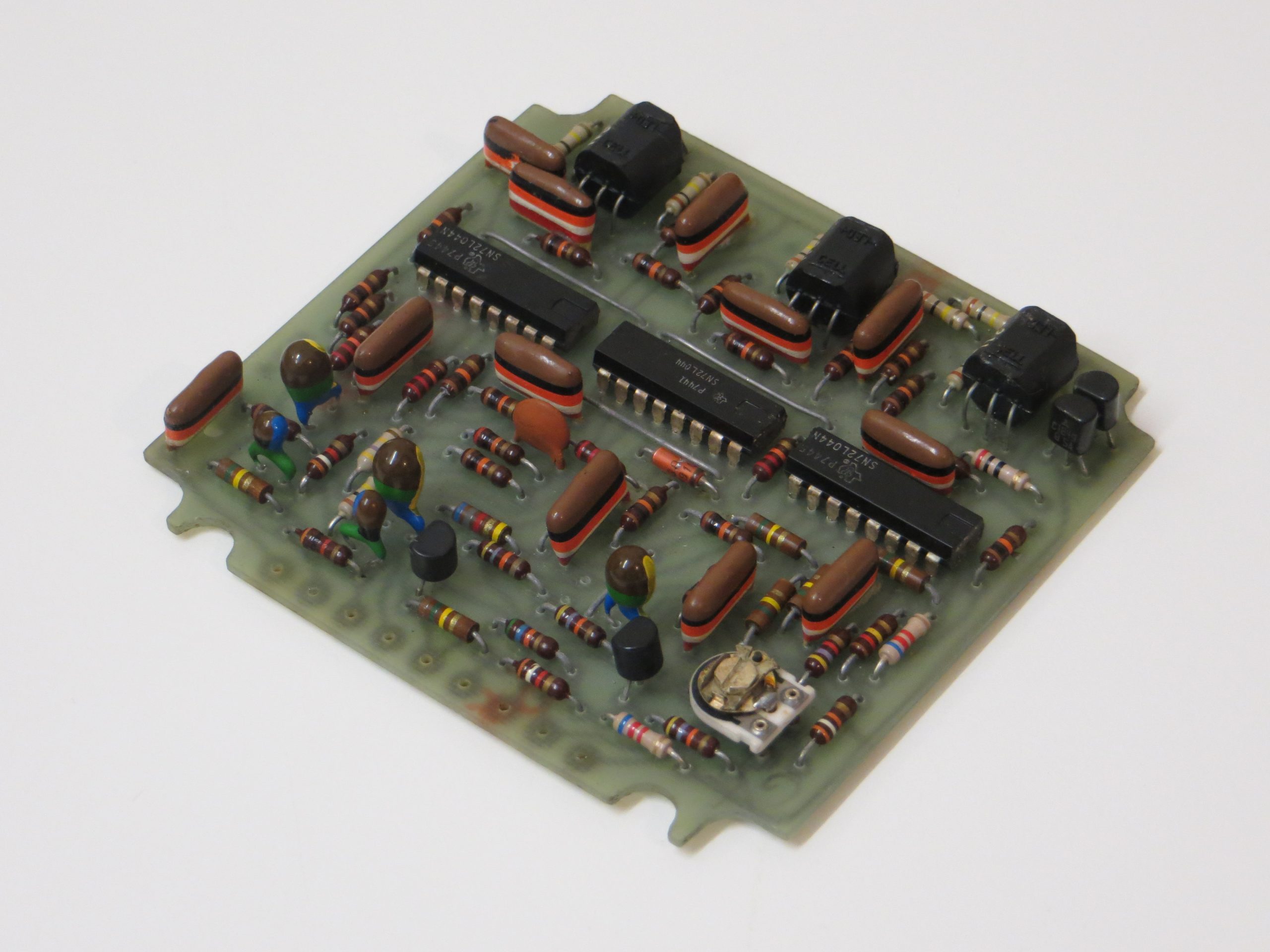
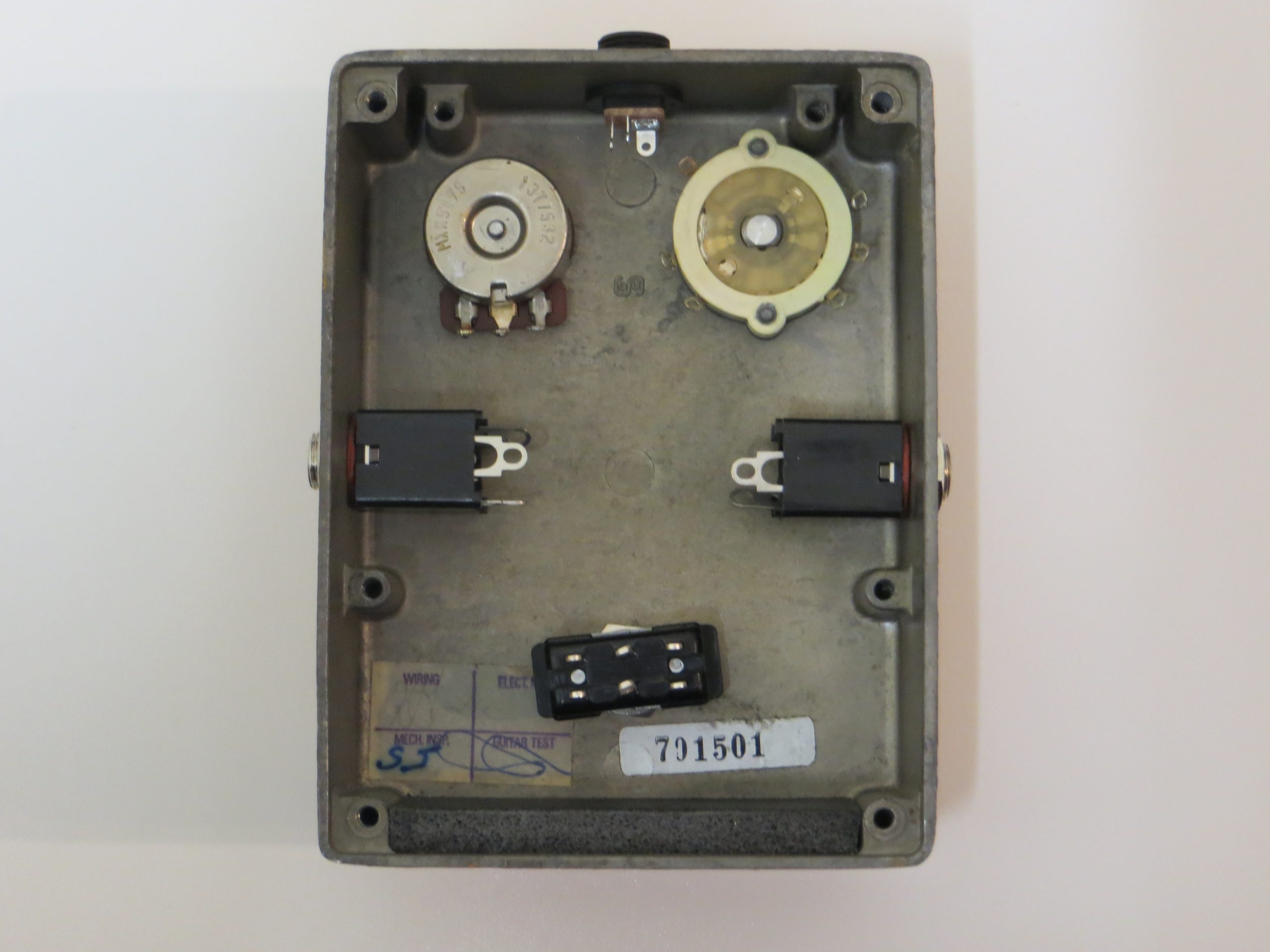
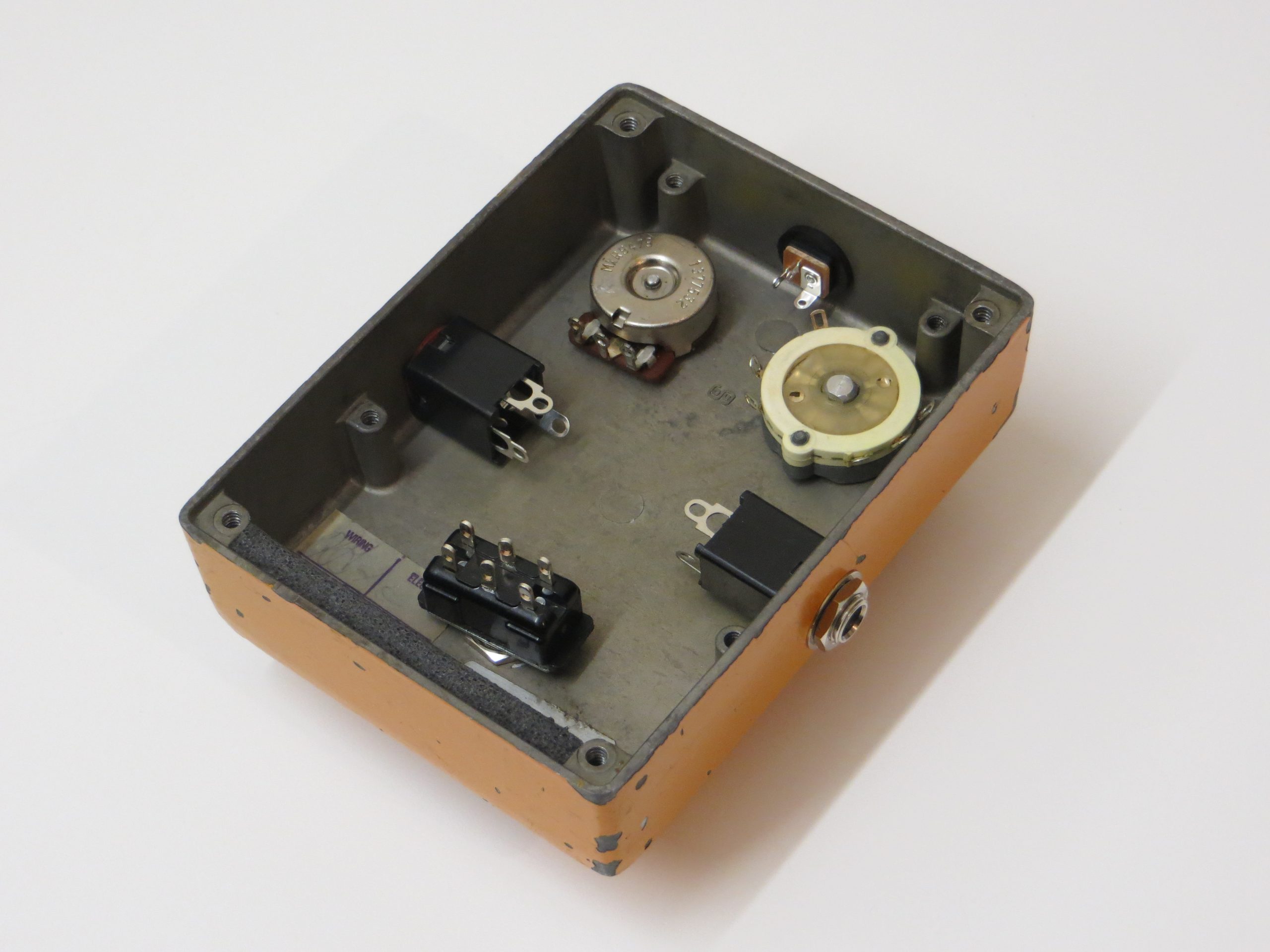
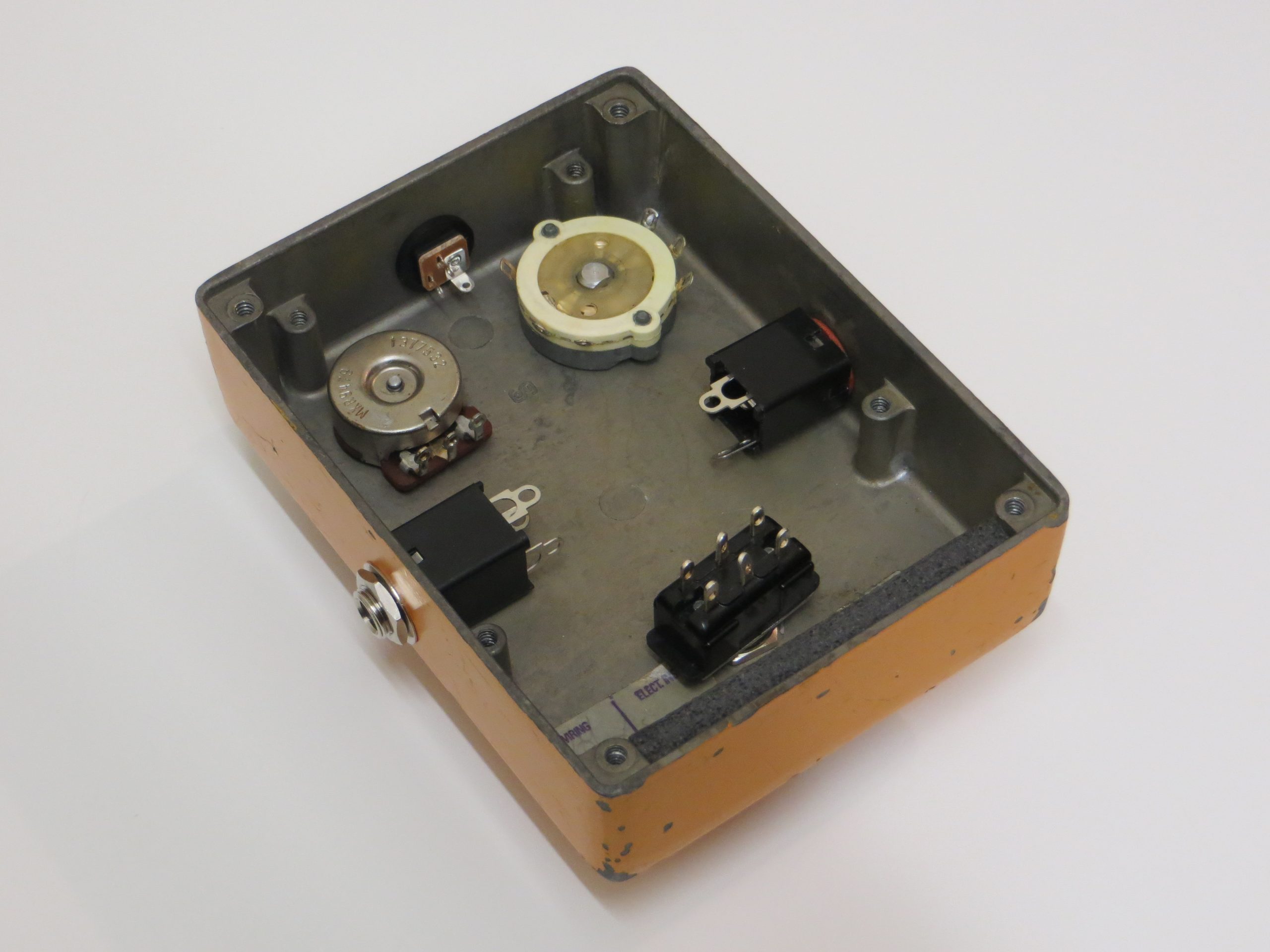
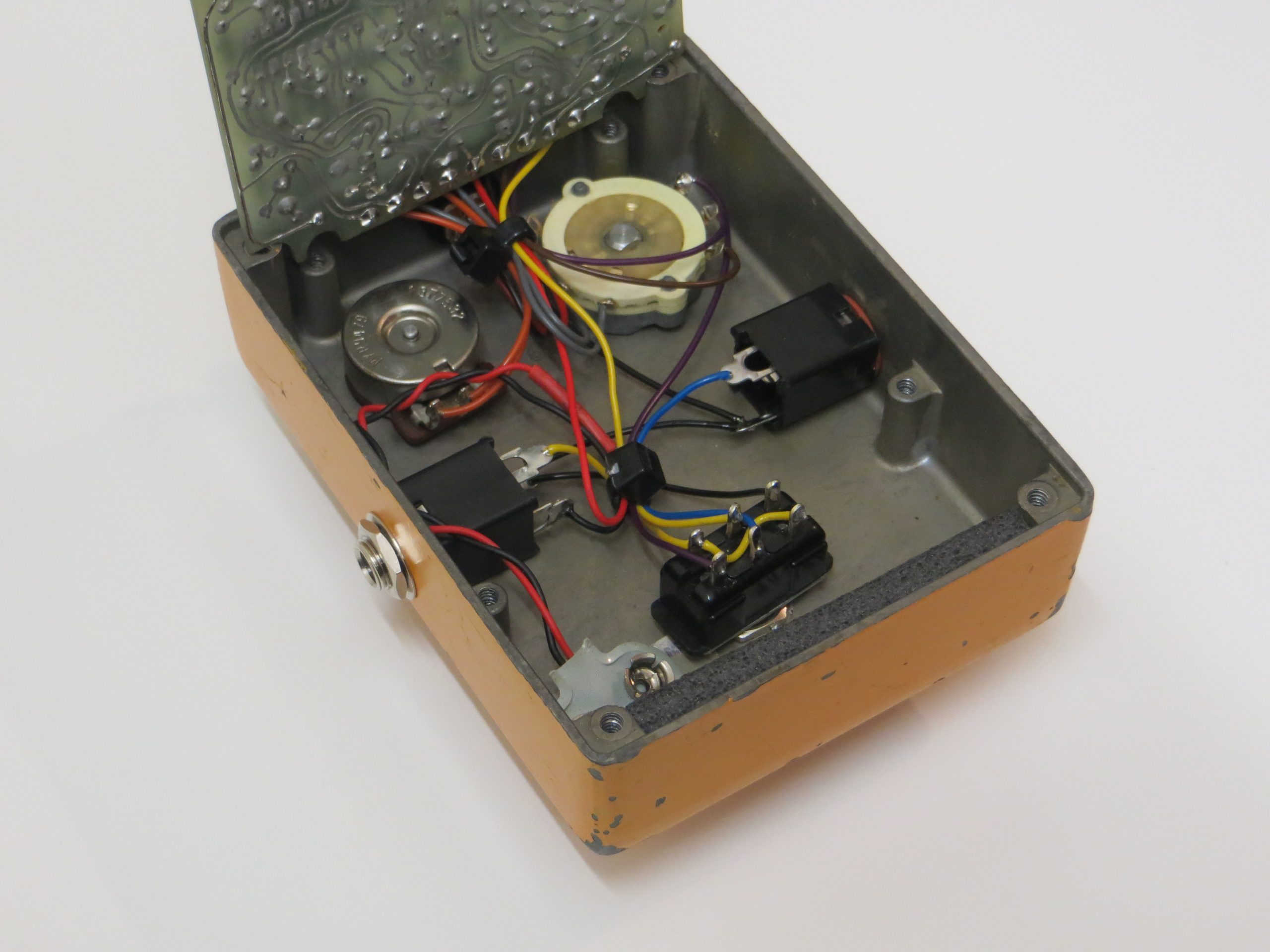
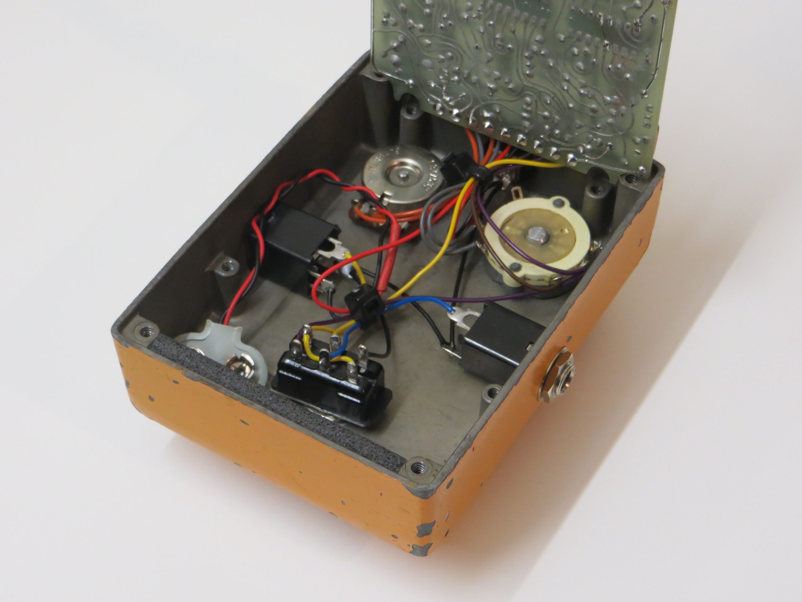
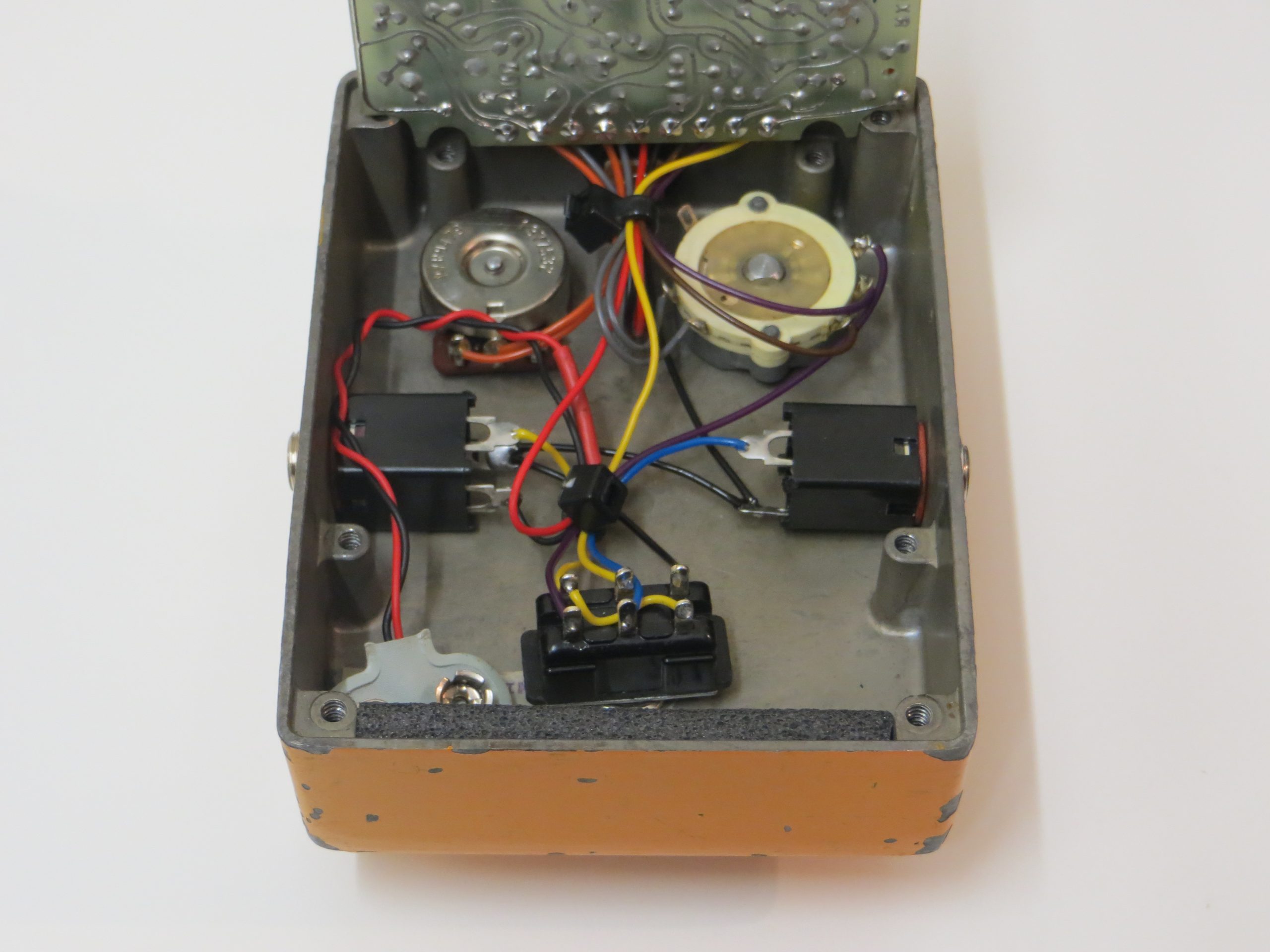
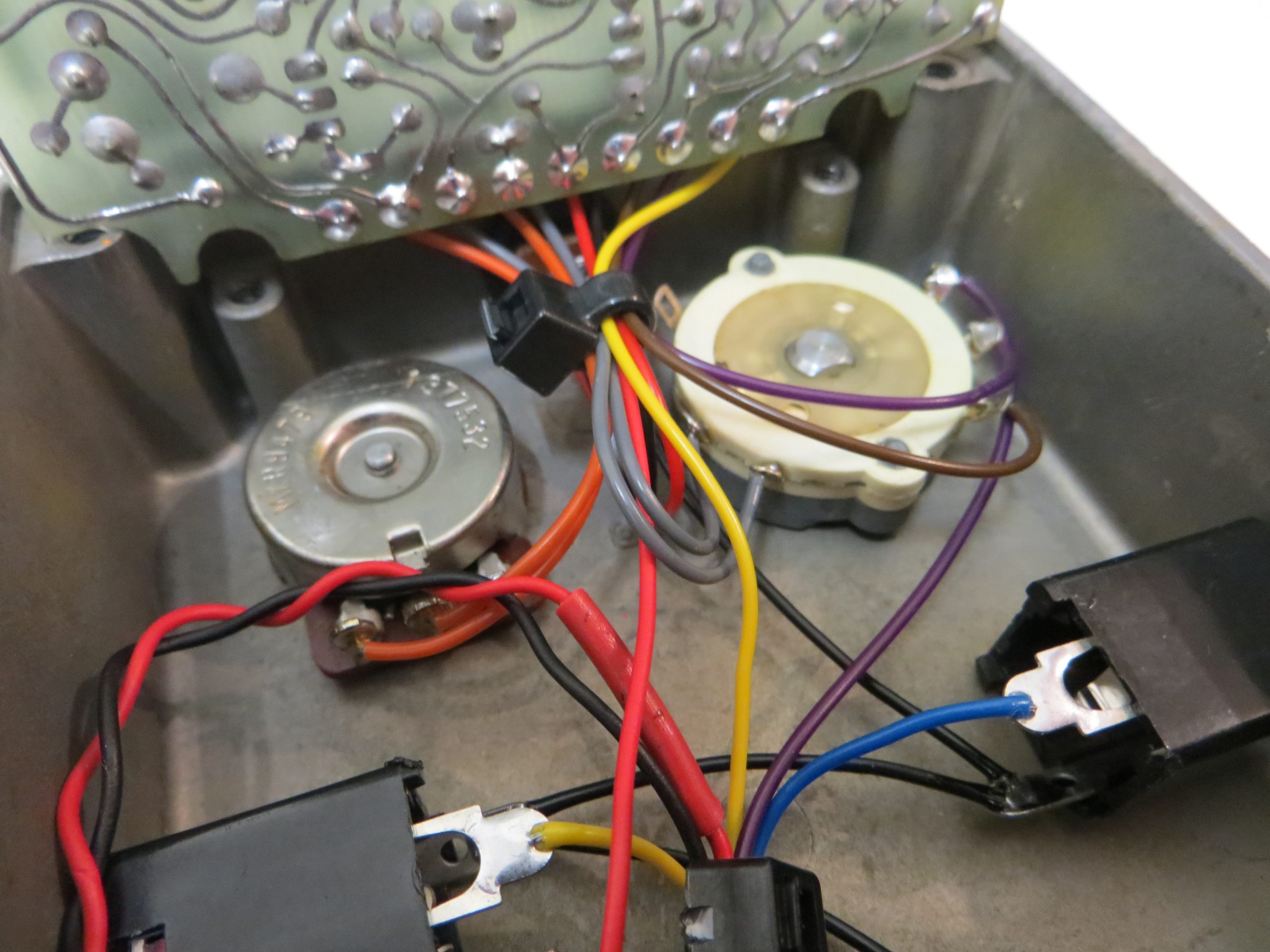
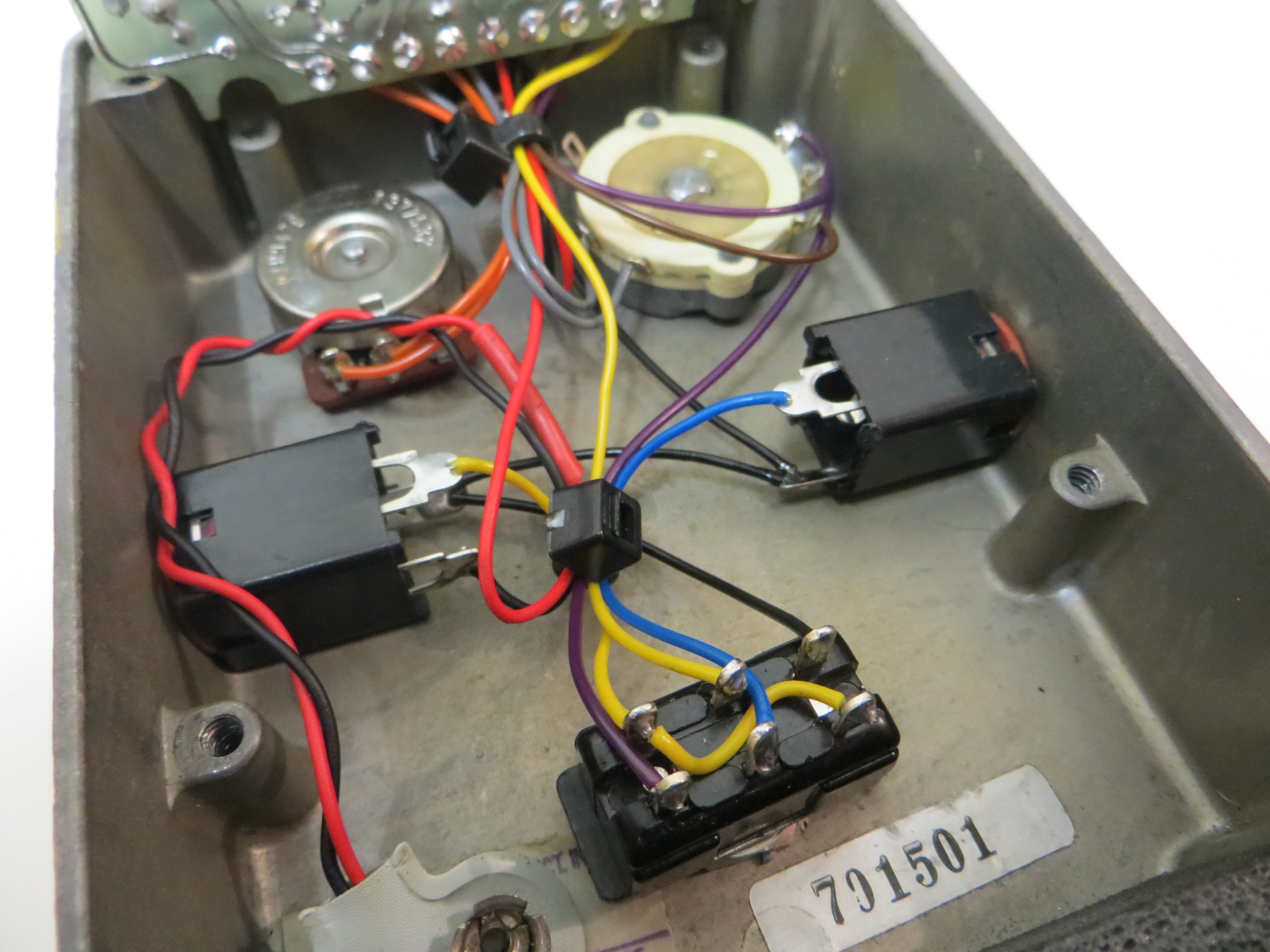
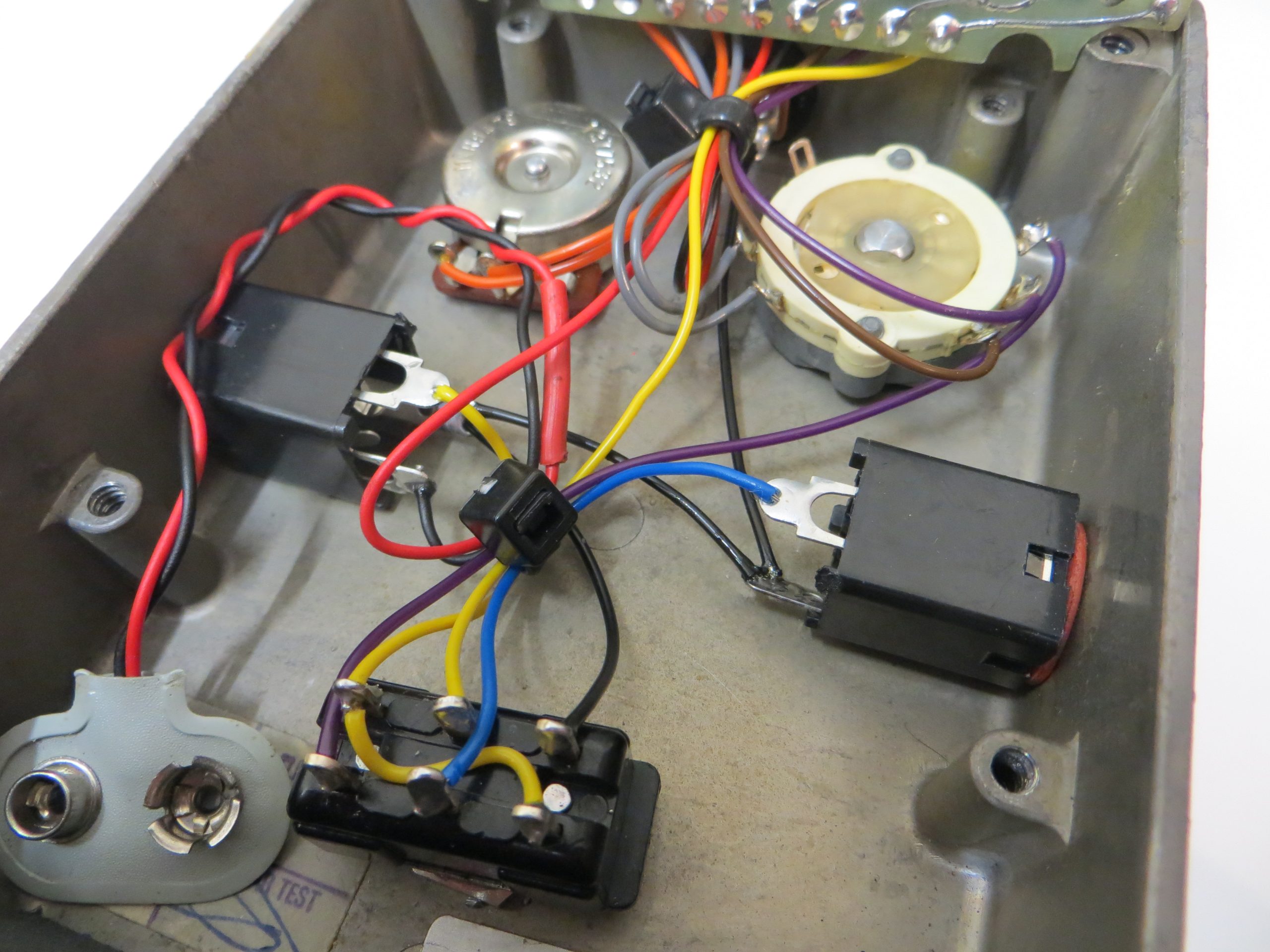
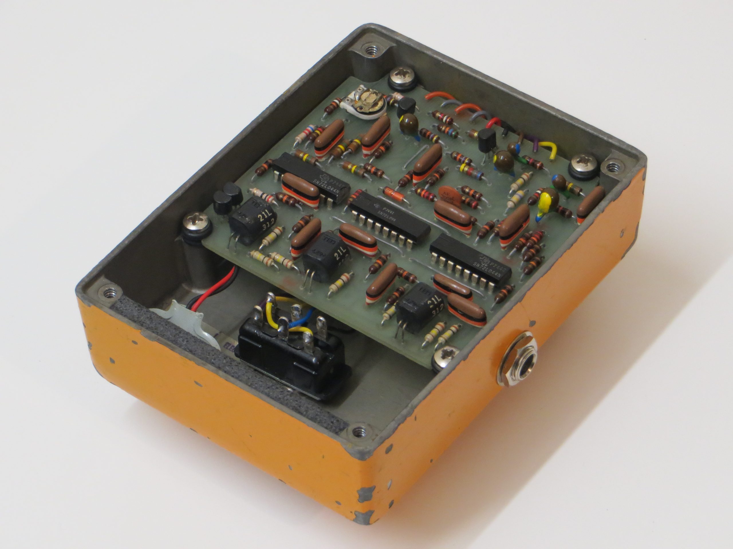
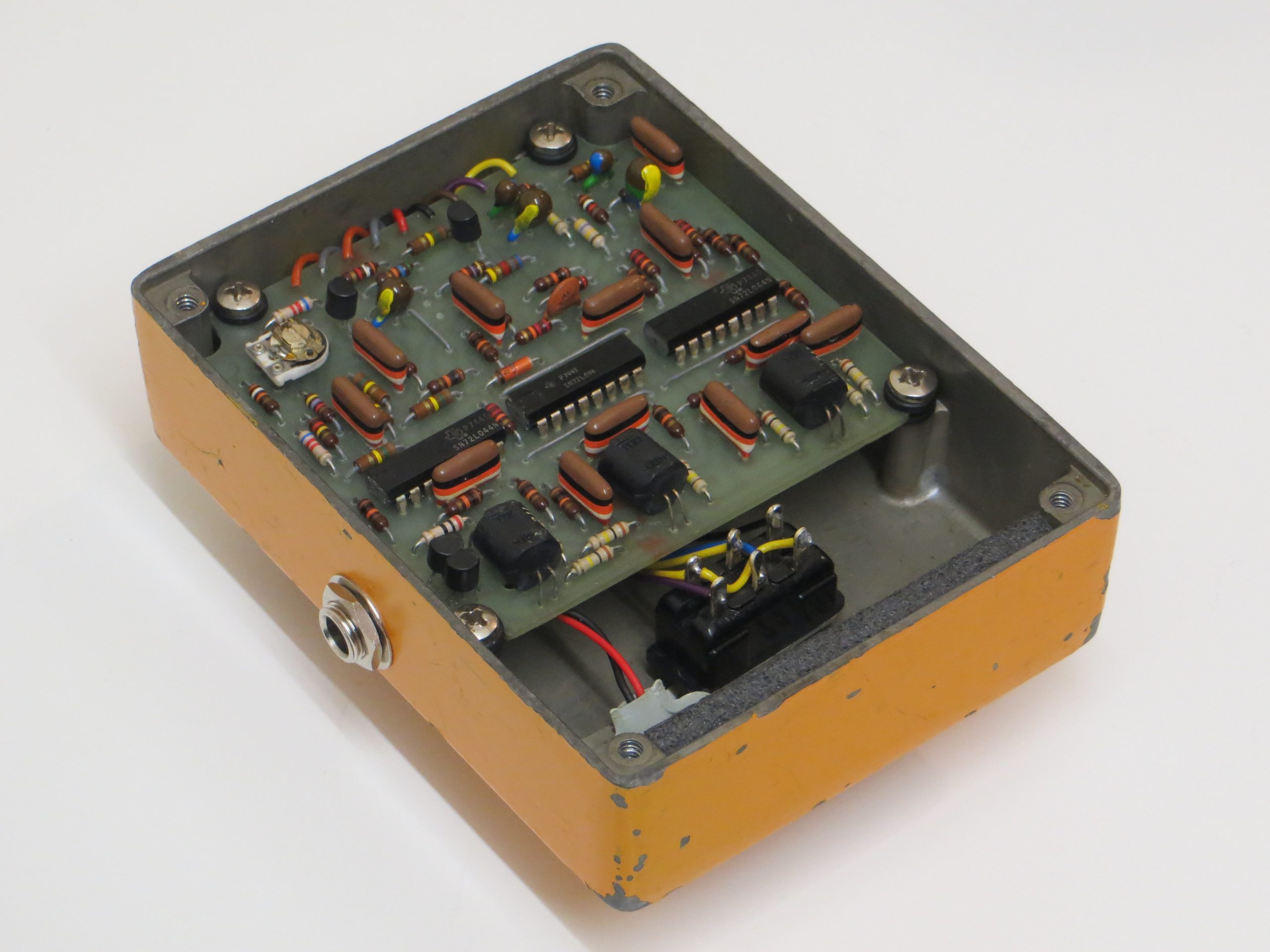
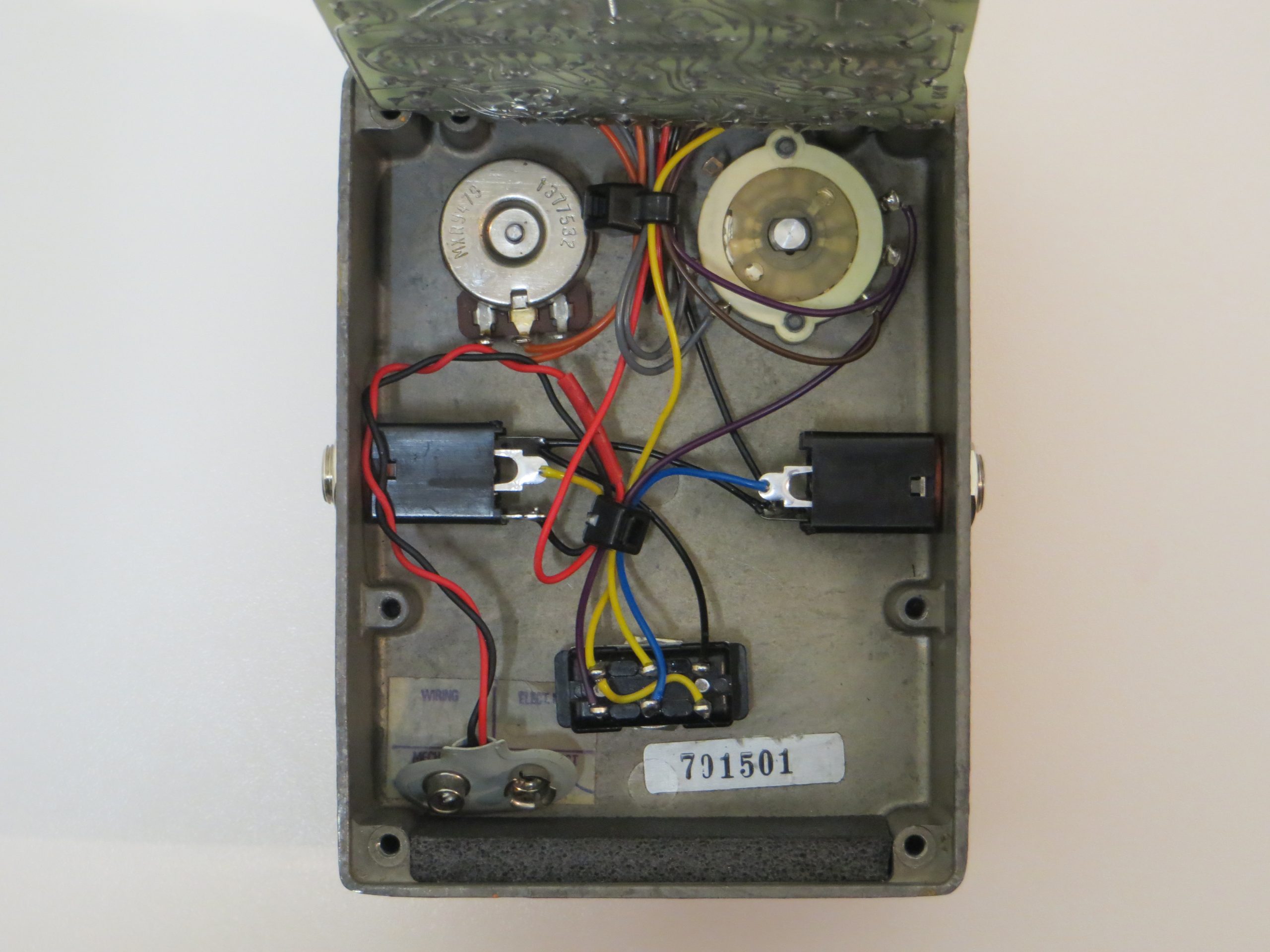
Let’s look at the pedal in its previously modded state. I no longer have any photos of the pedal in its pre 2000 state before the repair tech got his hands on it.
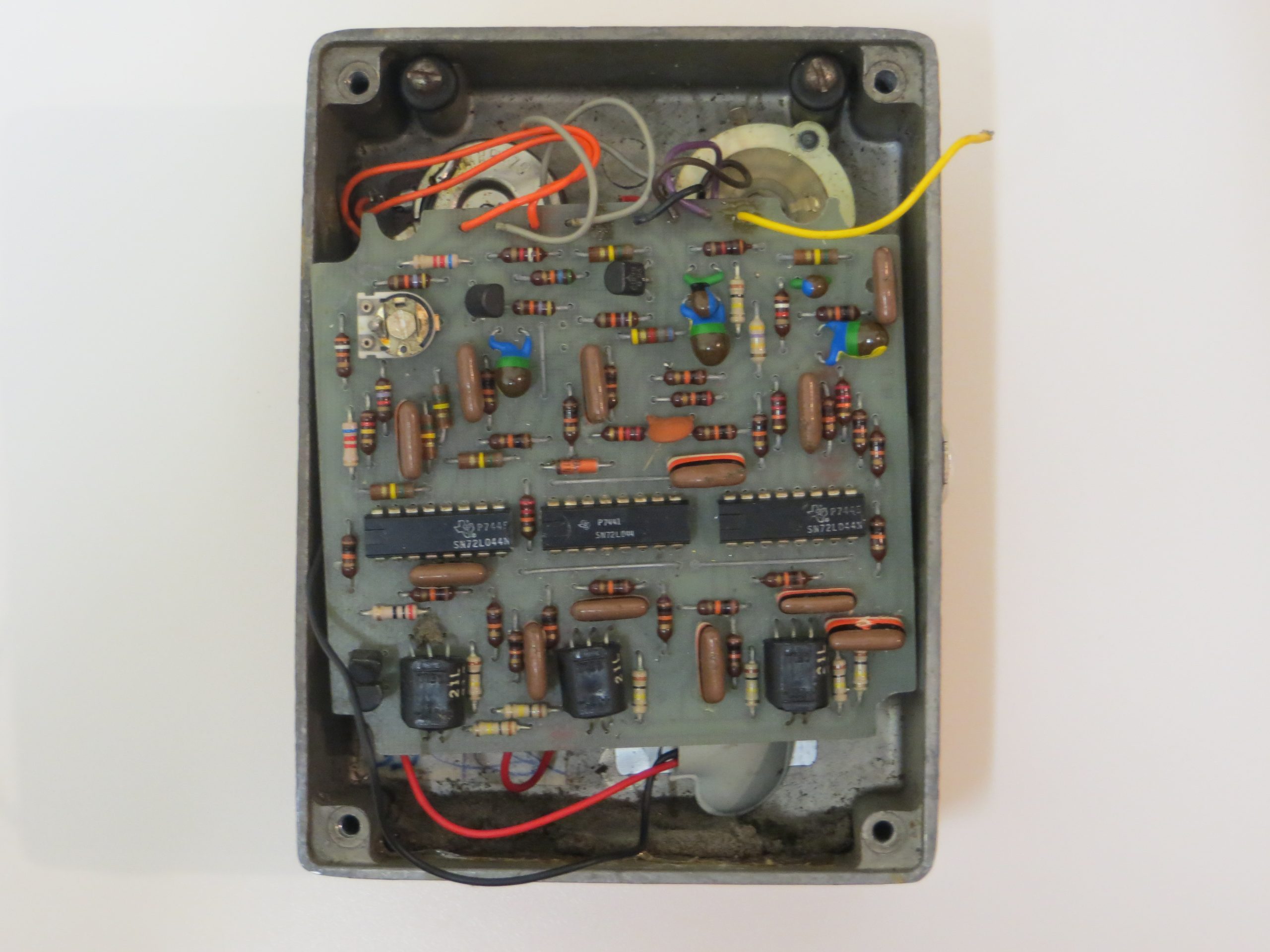
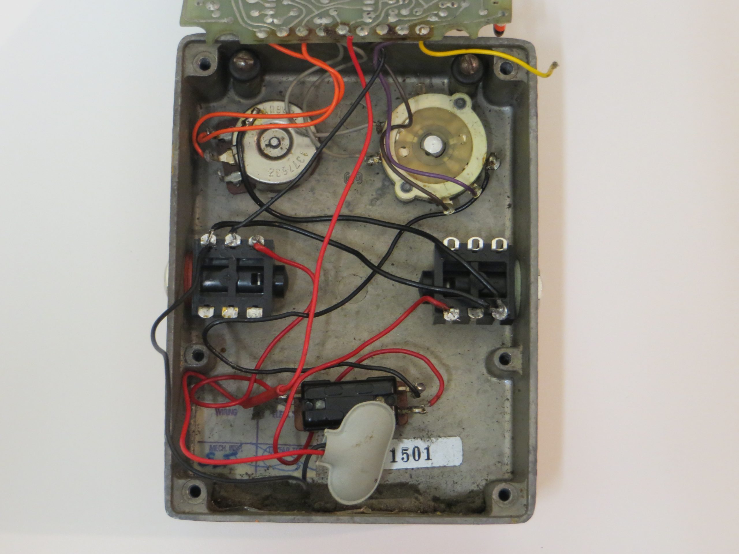
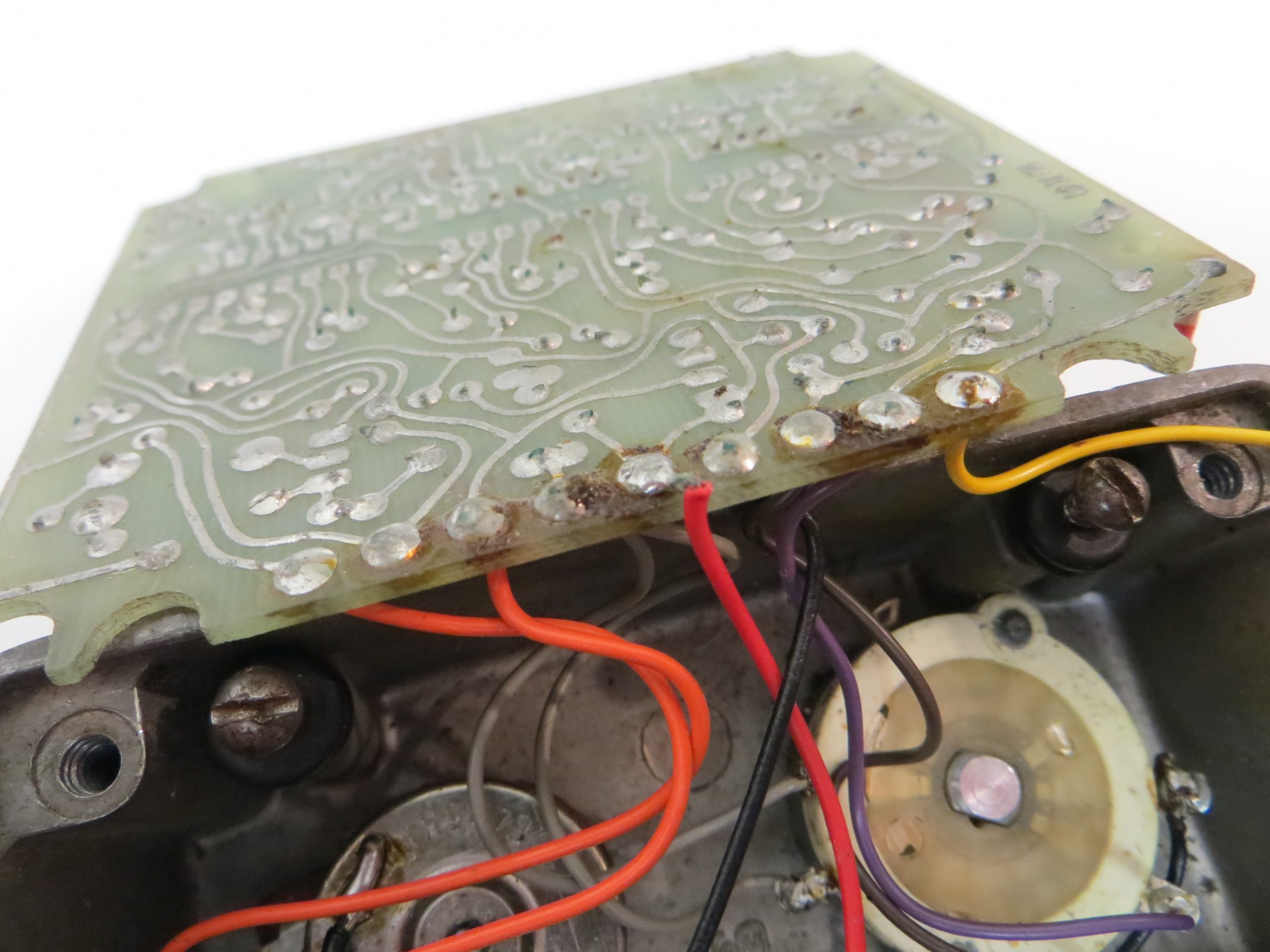
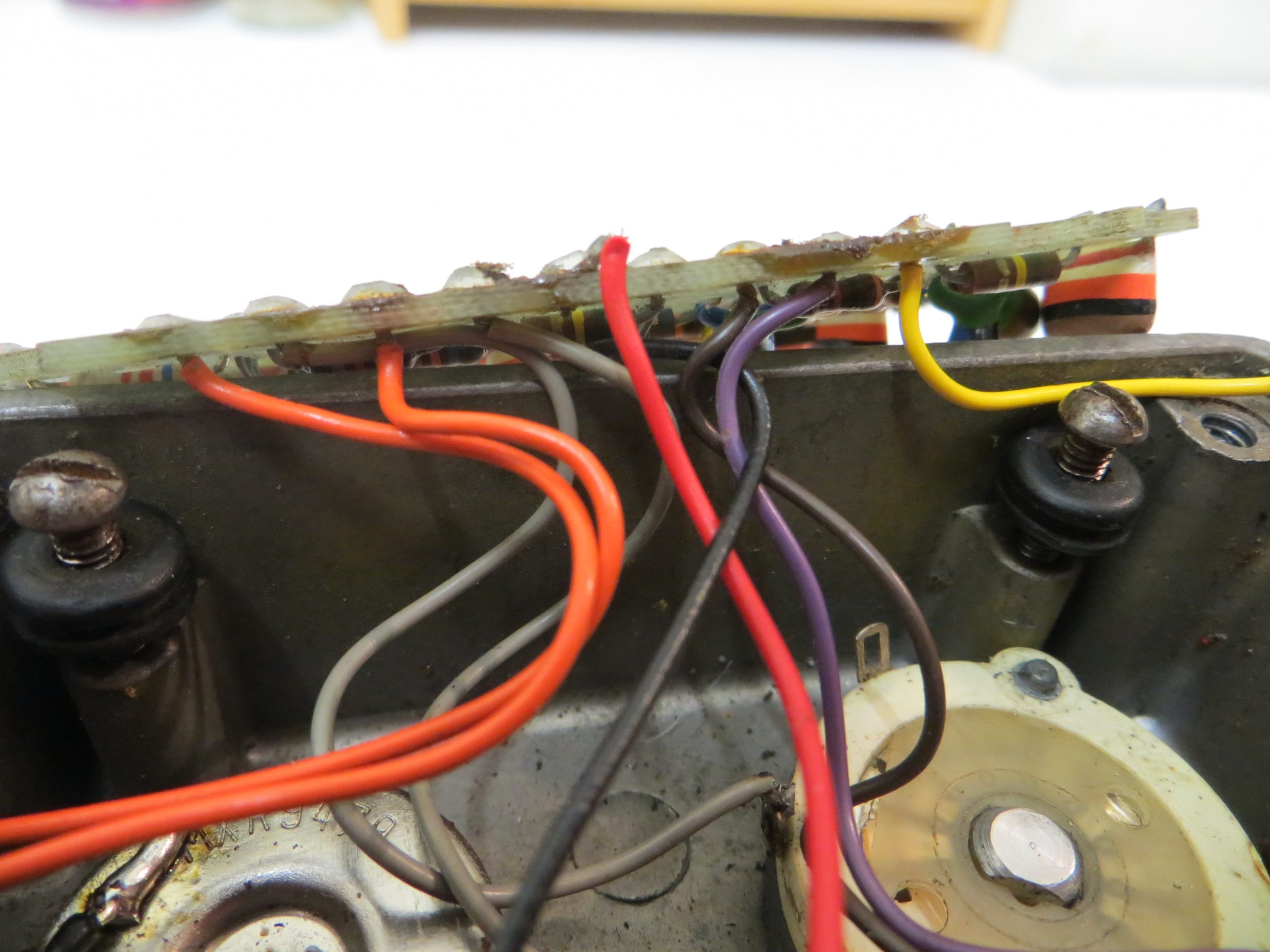
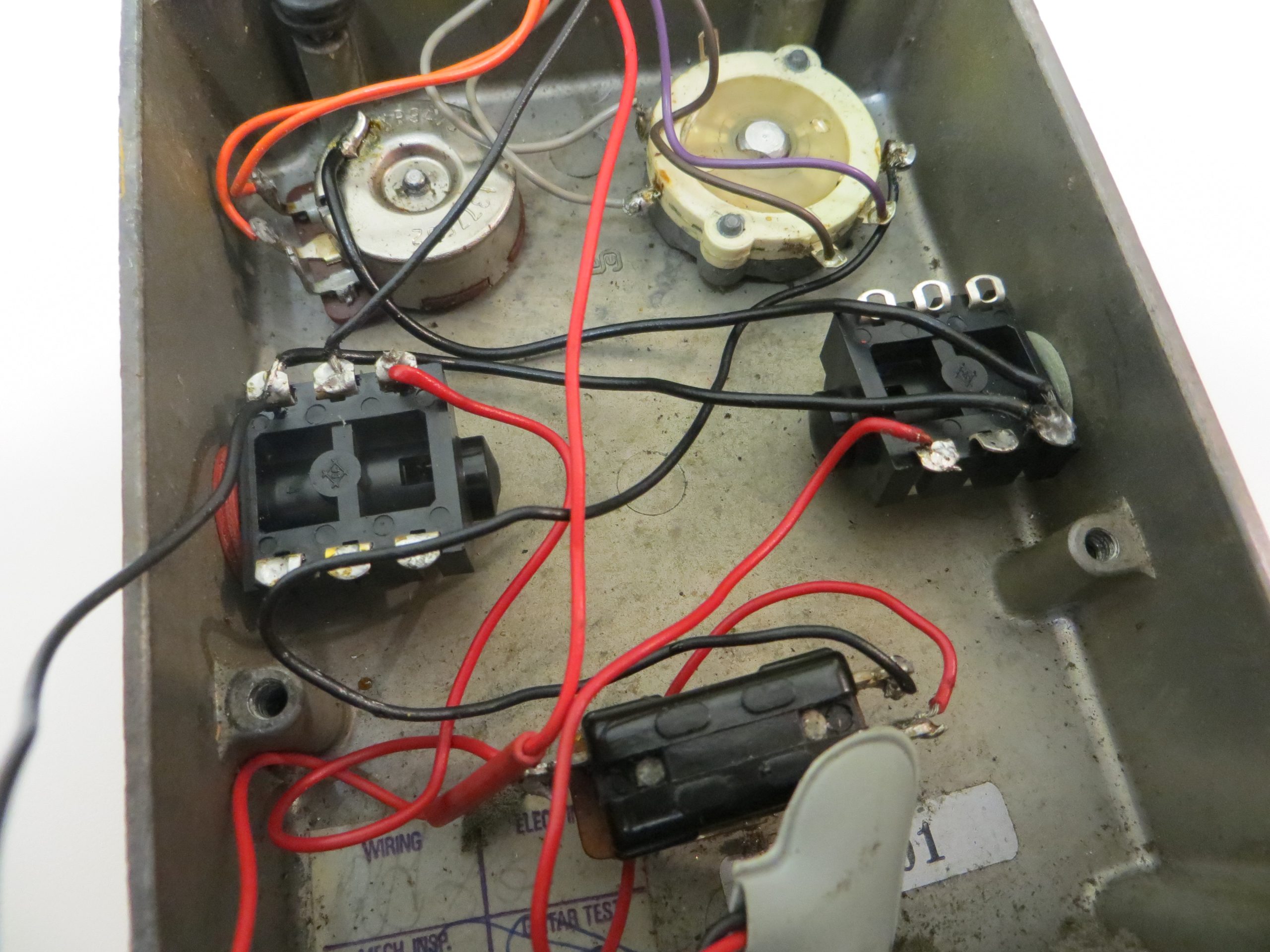
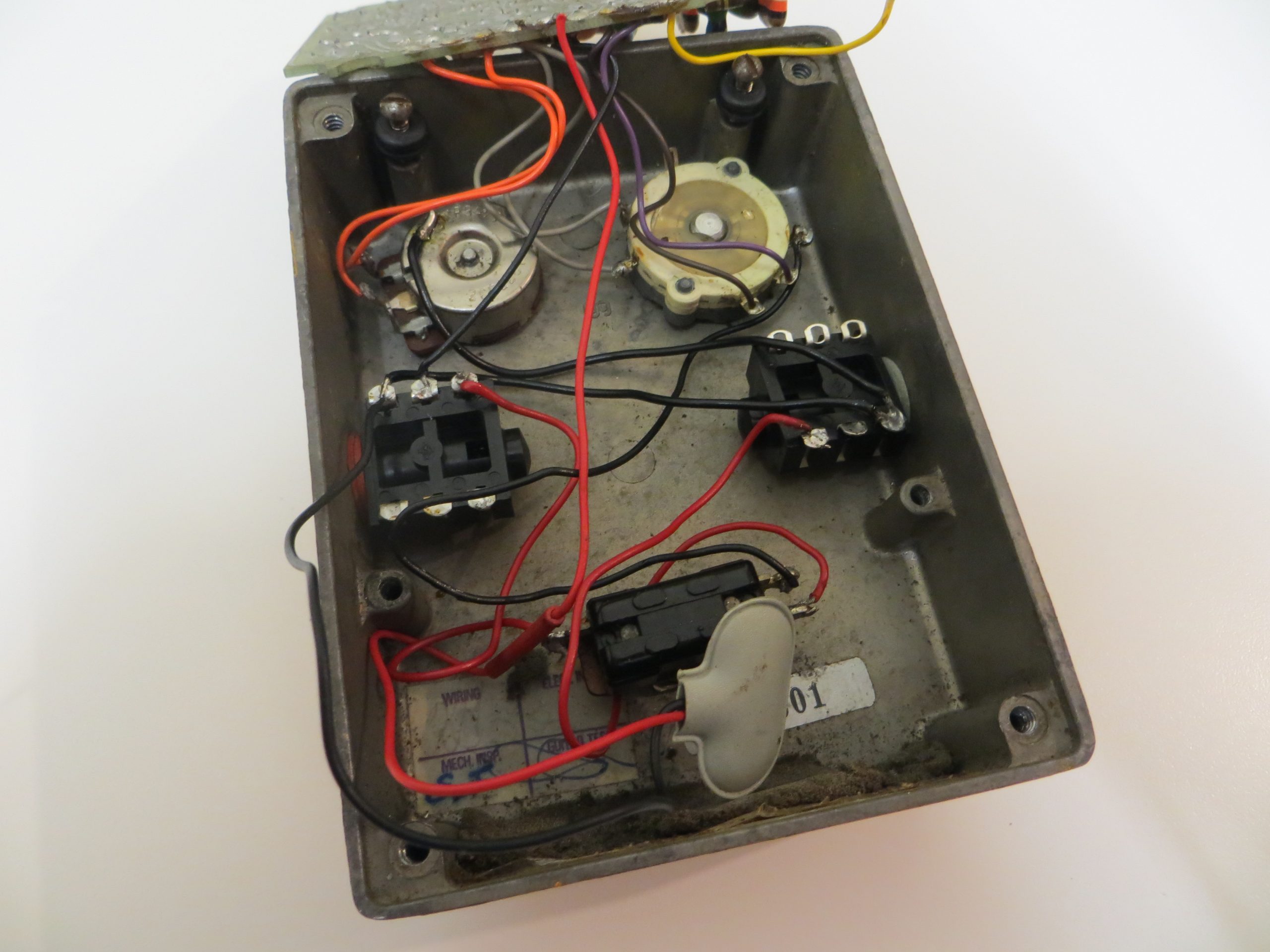
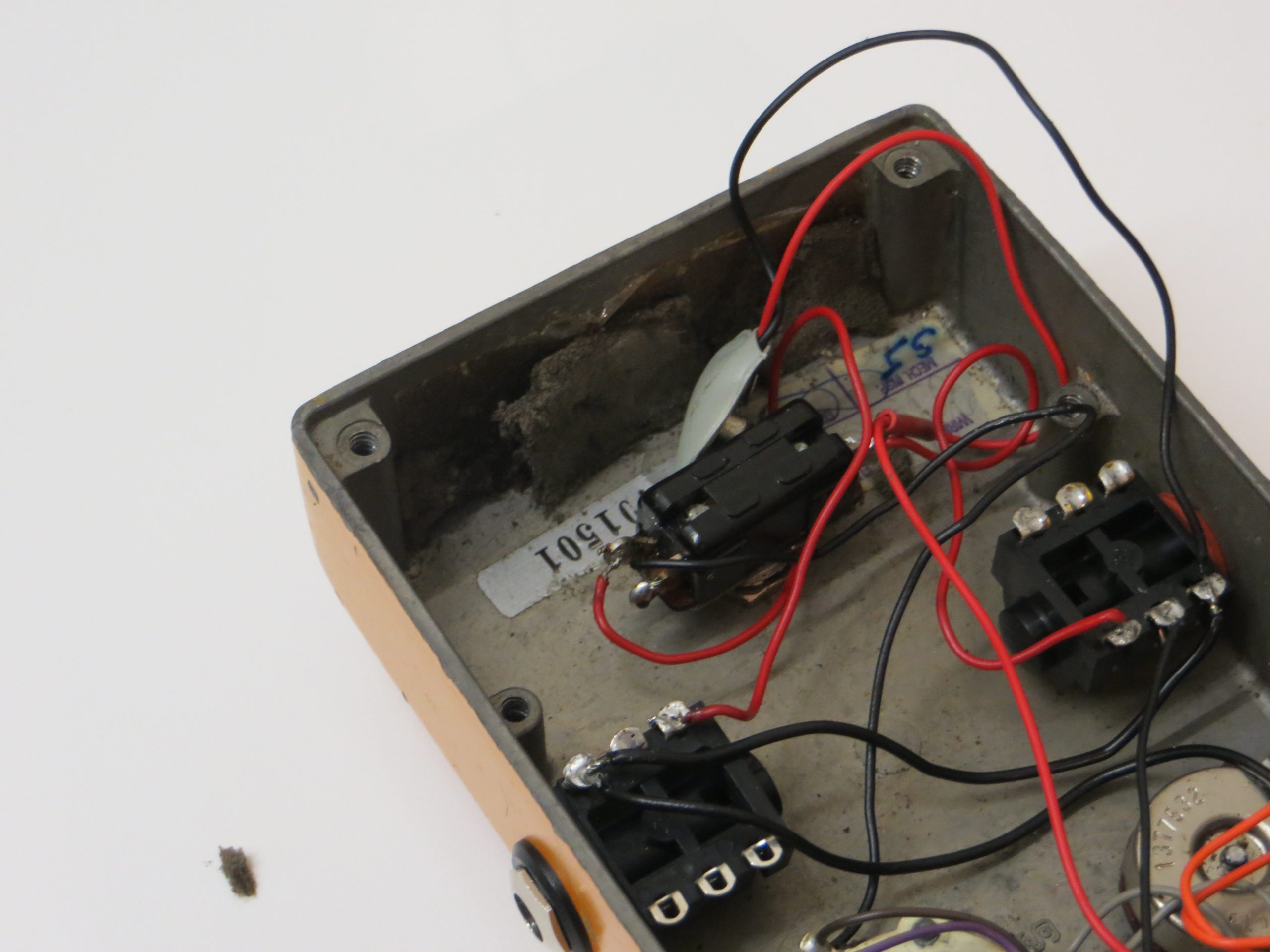
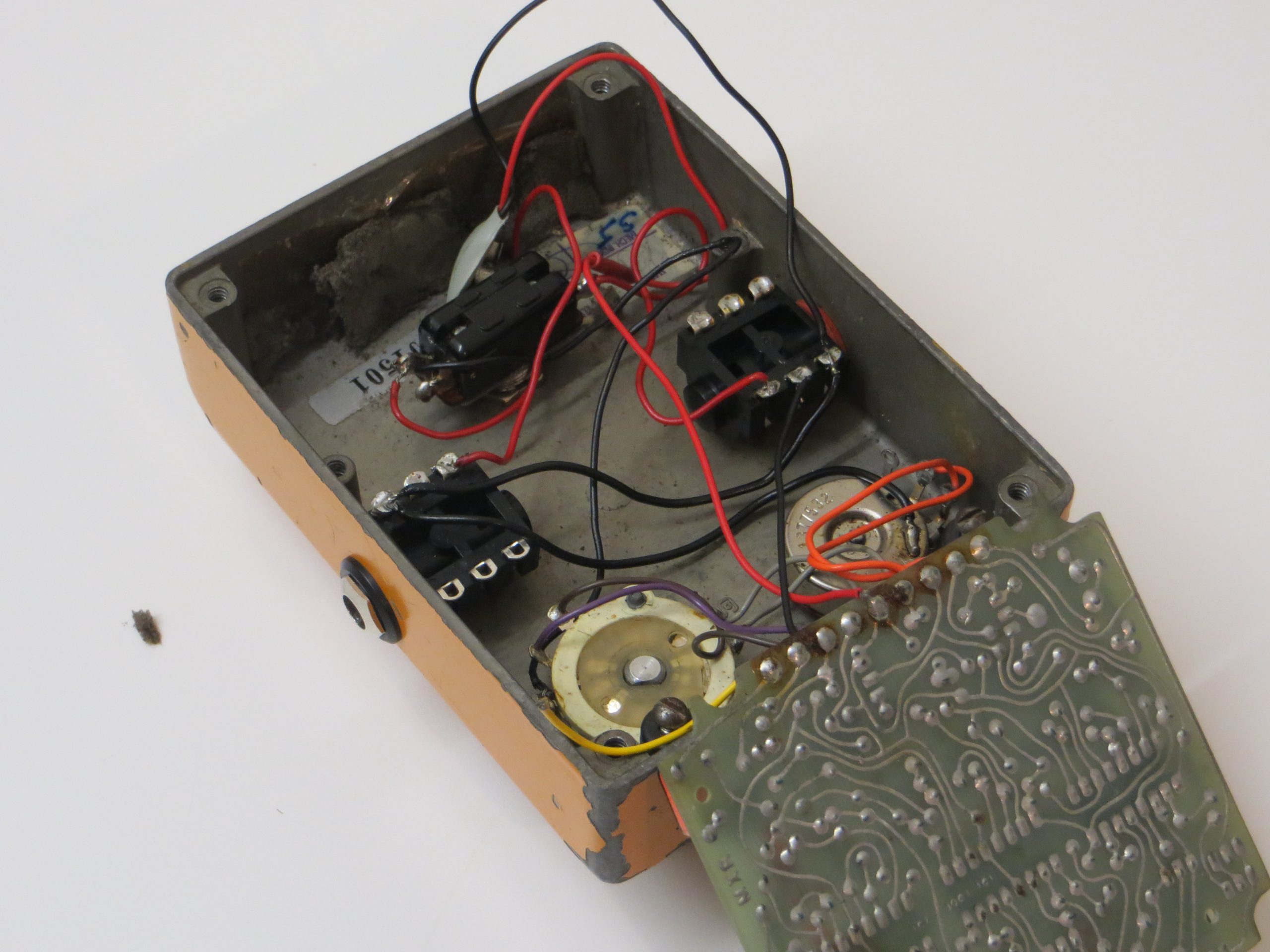
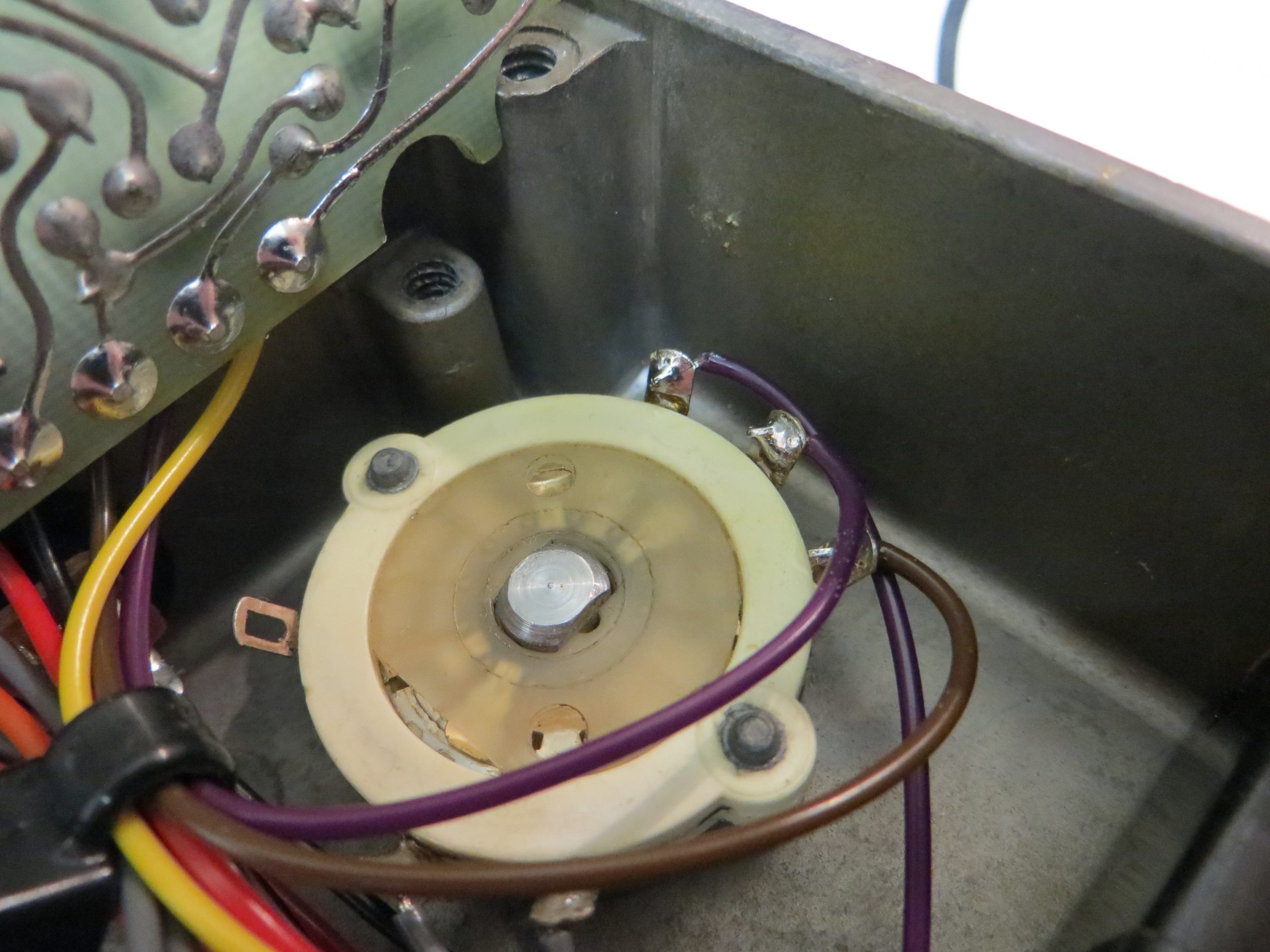
As you can see the previous work done on this pedal by the original owner and the repair technician has left the pedal in a very bad state. It’s a mess of bad soldering, rusting & brittle old wires, and cheap replacement components.
The new jack sockets look like unbranded ones and they are not the correct type for this pedal. It would be quite easy for the PCB to short against the jack socket solder lugs. The soldering throughout is really poor with old, tarnished solder and flux not cleaned away and wires lightly tacked in on top of this bad solder. The PCB is also not secured in place as the original screws for this have been lost.
My goal for this pedal is for it to be completely cleaned and re-wired so it looks like it has just left the factory. I want to mod it for True Bypass and add a DC socket so it can run off a power supply. I want to replace any missing parts with equal or better quality than the original MXR part and get this pedal back to fully functioning and reliable operation.
Let’s Begin
The first thing I did was clean and completely dismantle the pedal.
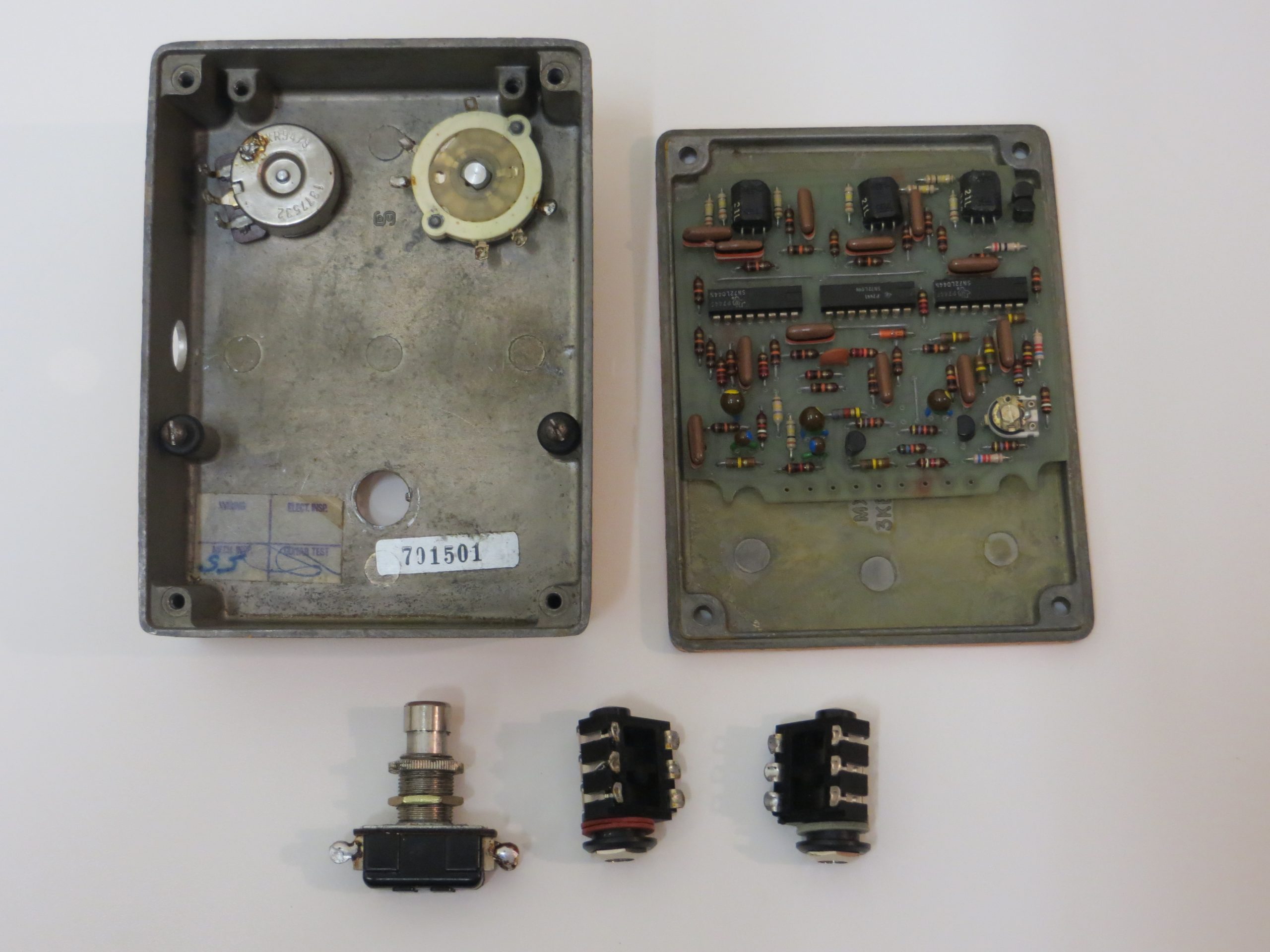
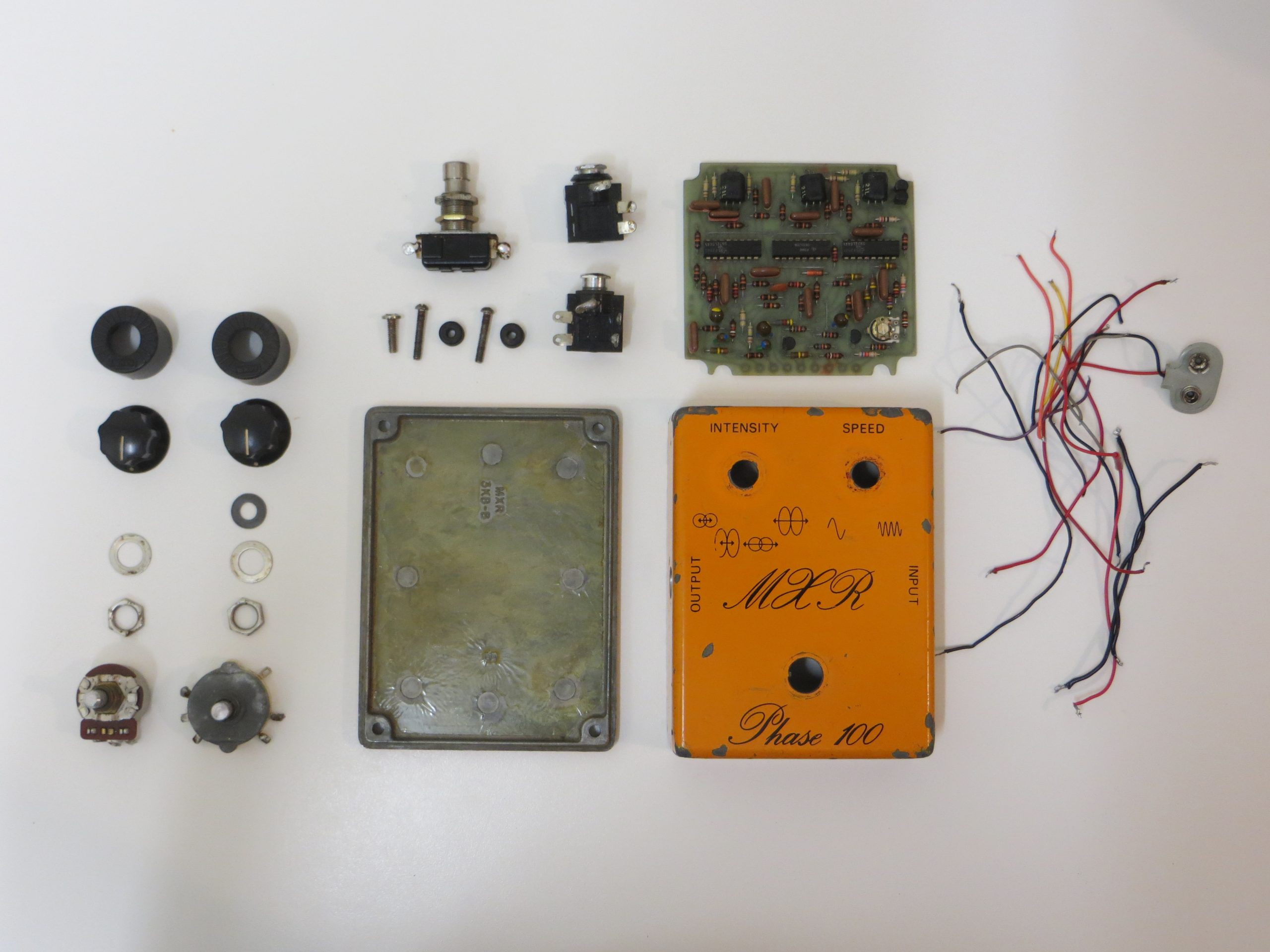
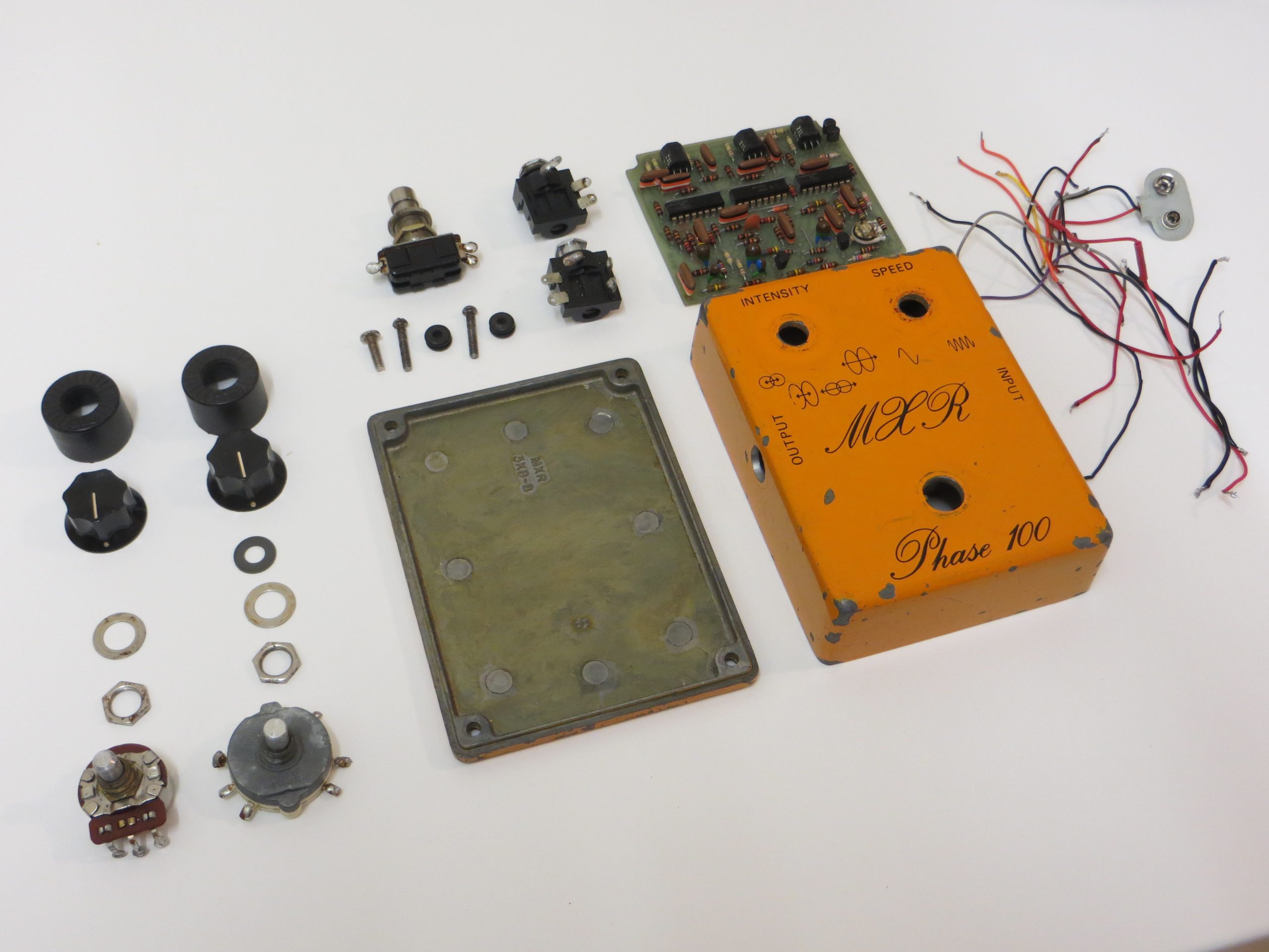
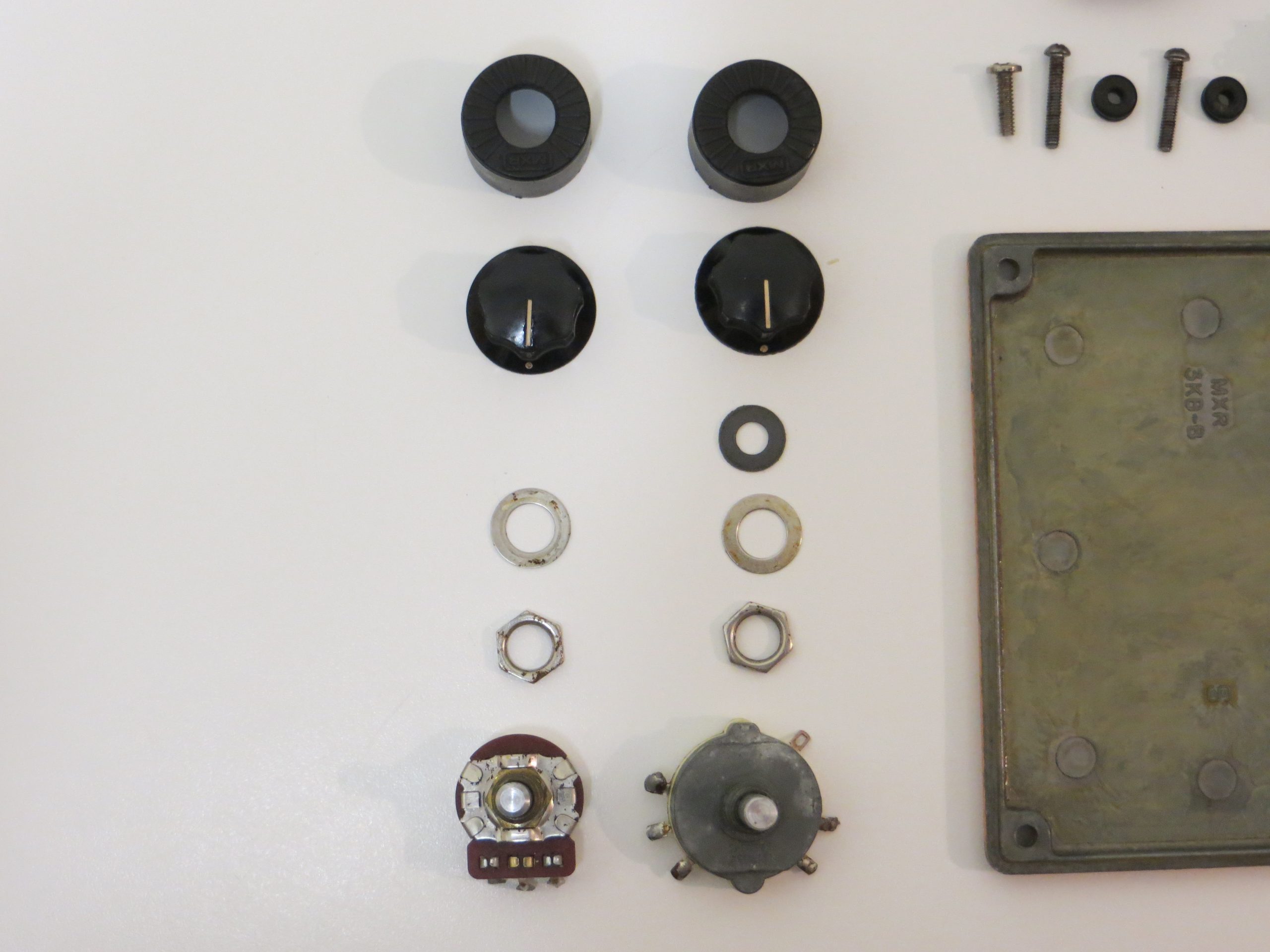
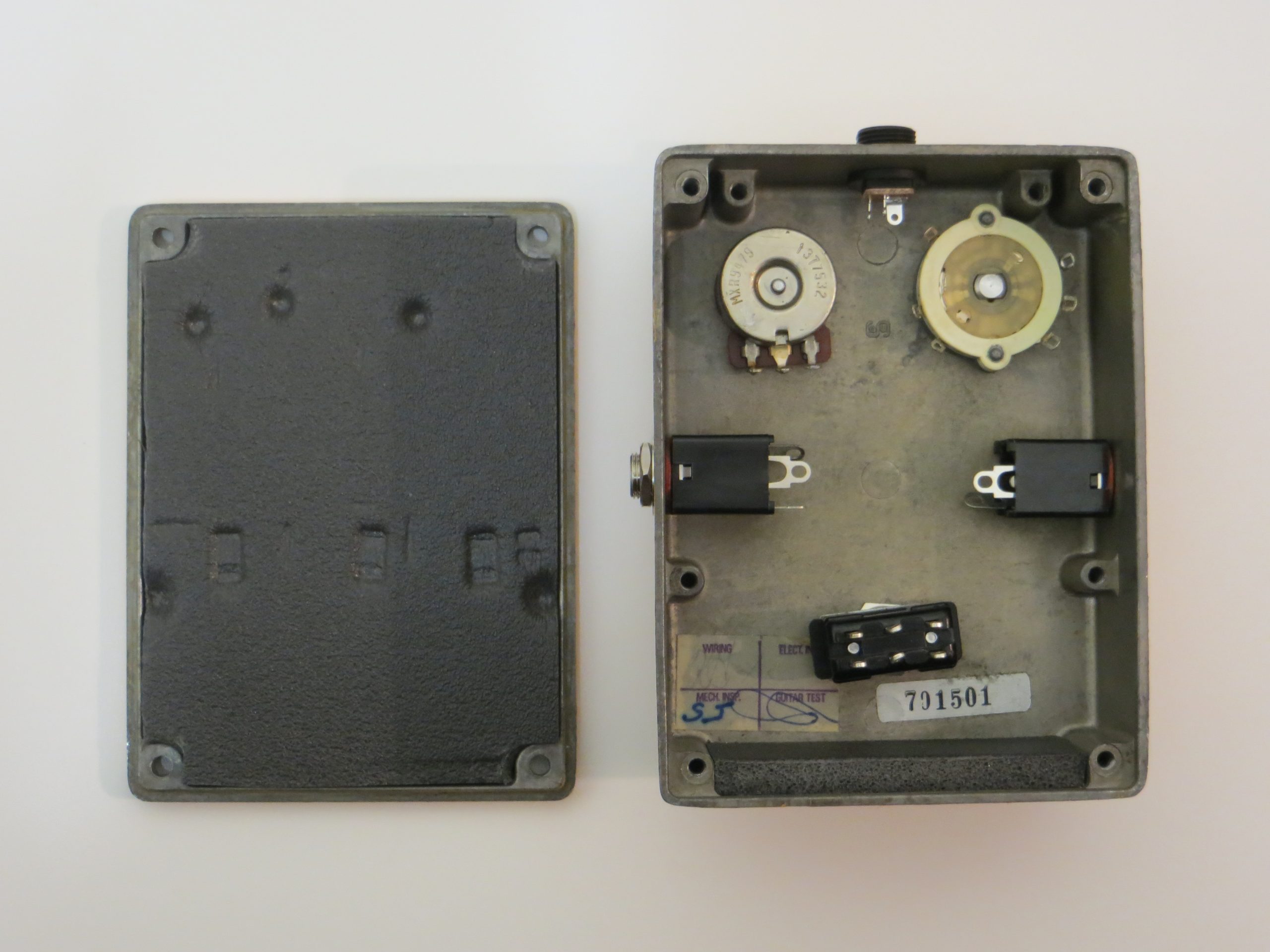
I am left with the following.
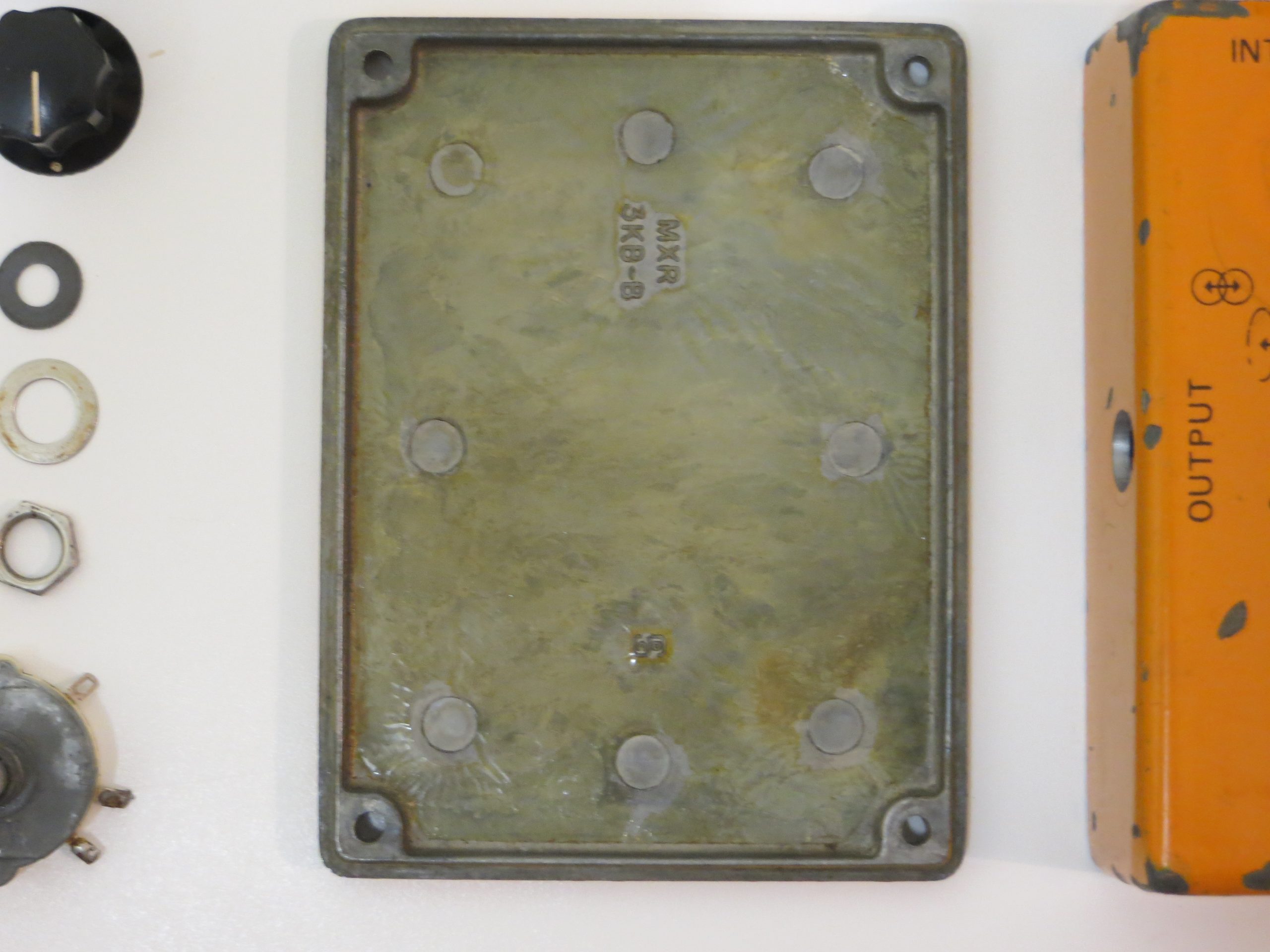
- Enclosure Main
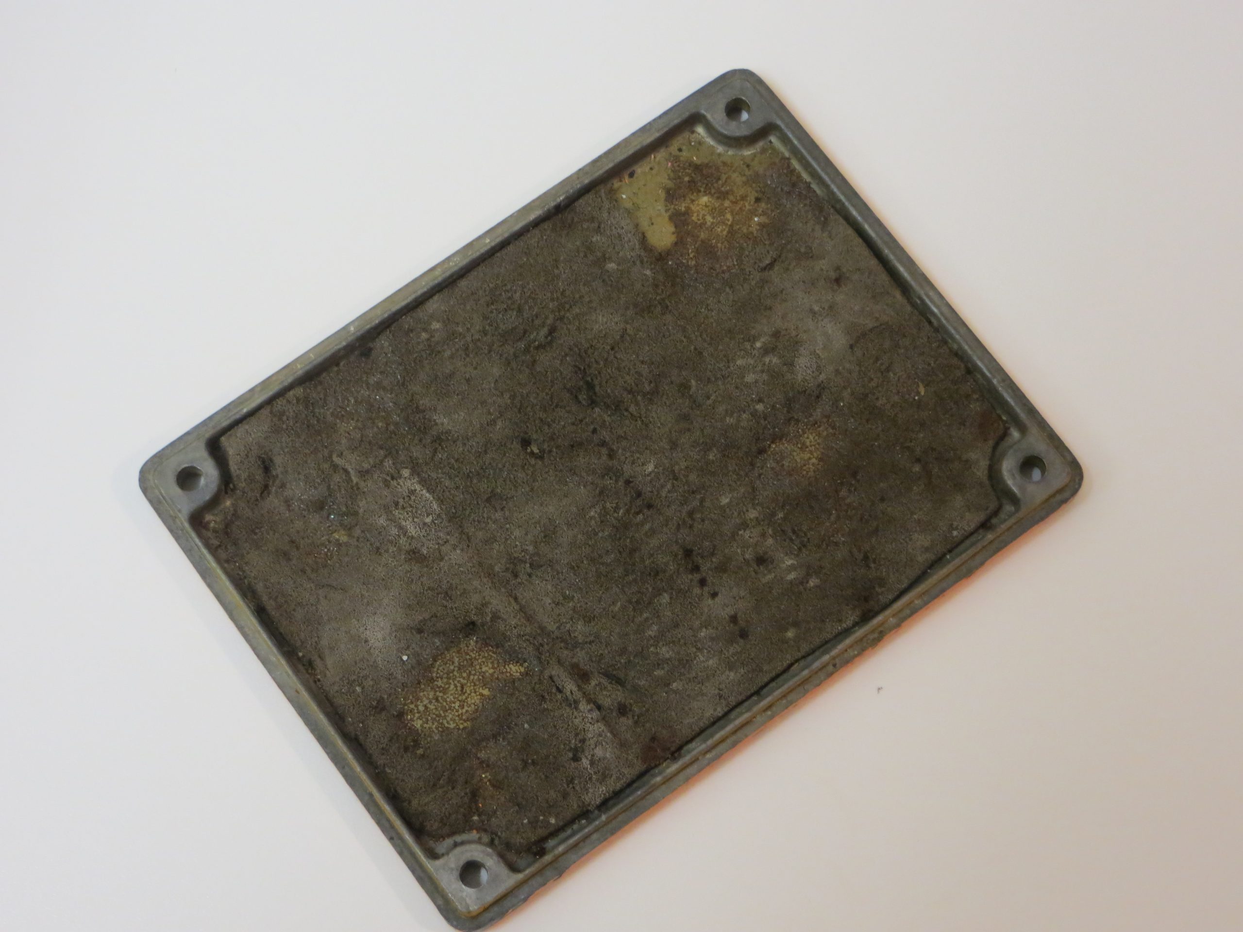
- Enclosure Back Plate
- PCB with Components
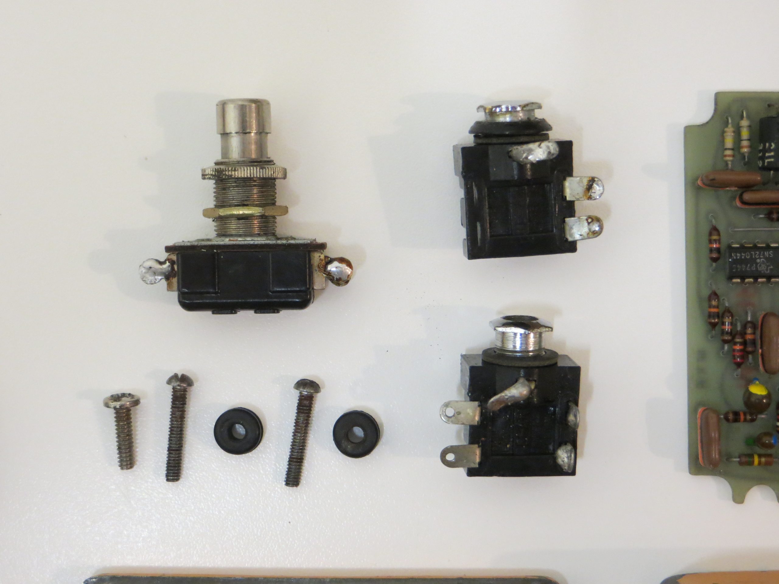
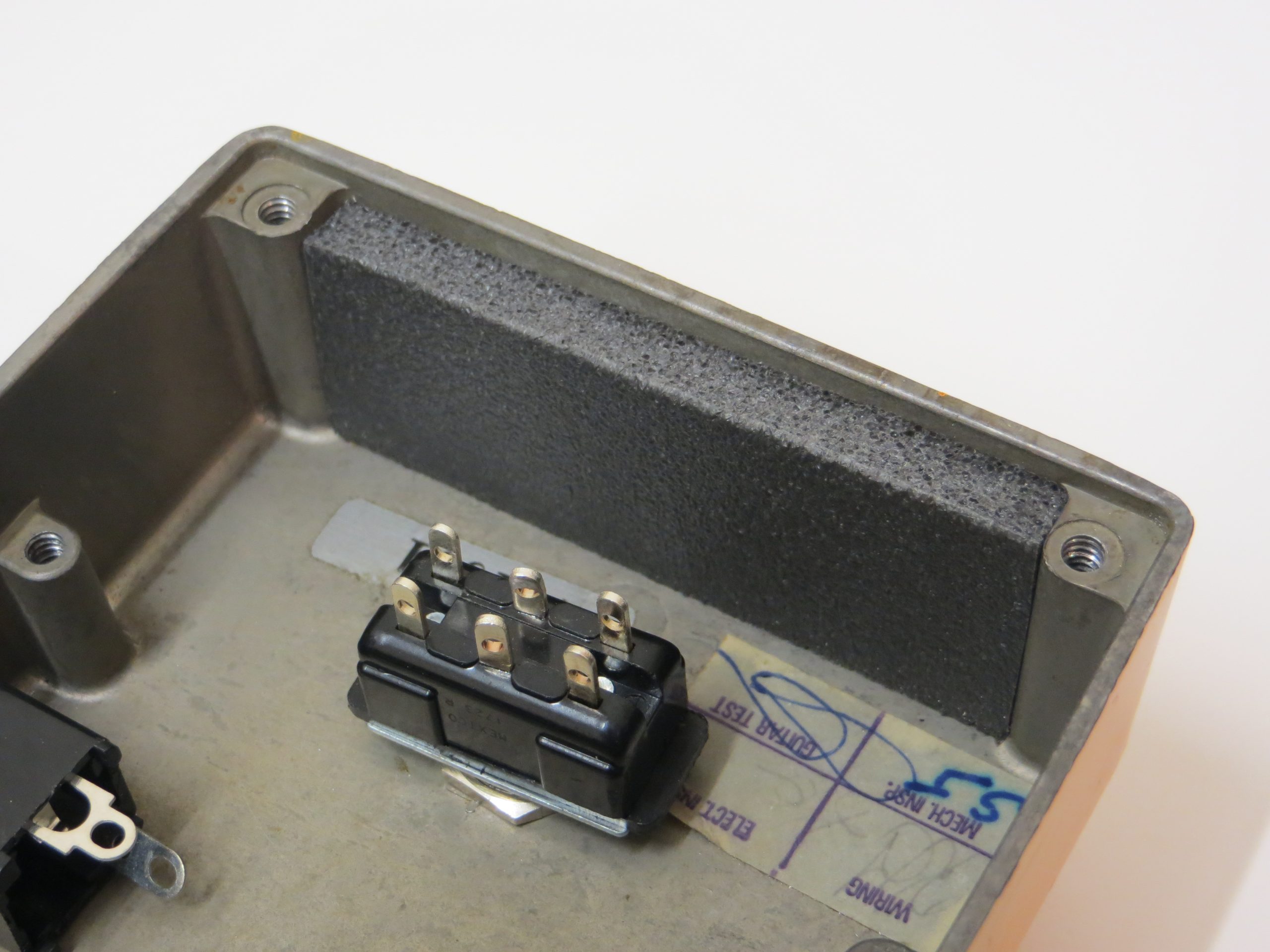
- 1 x Carling SPDT Switch
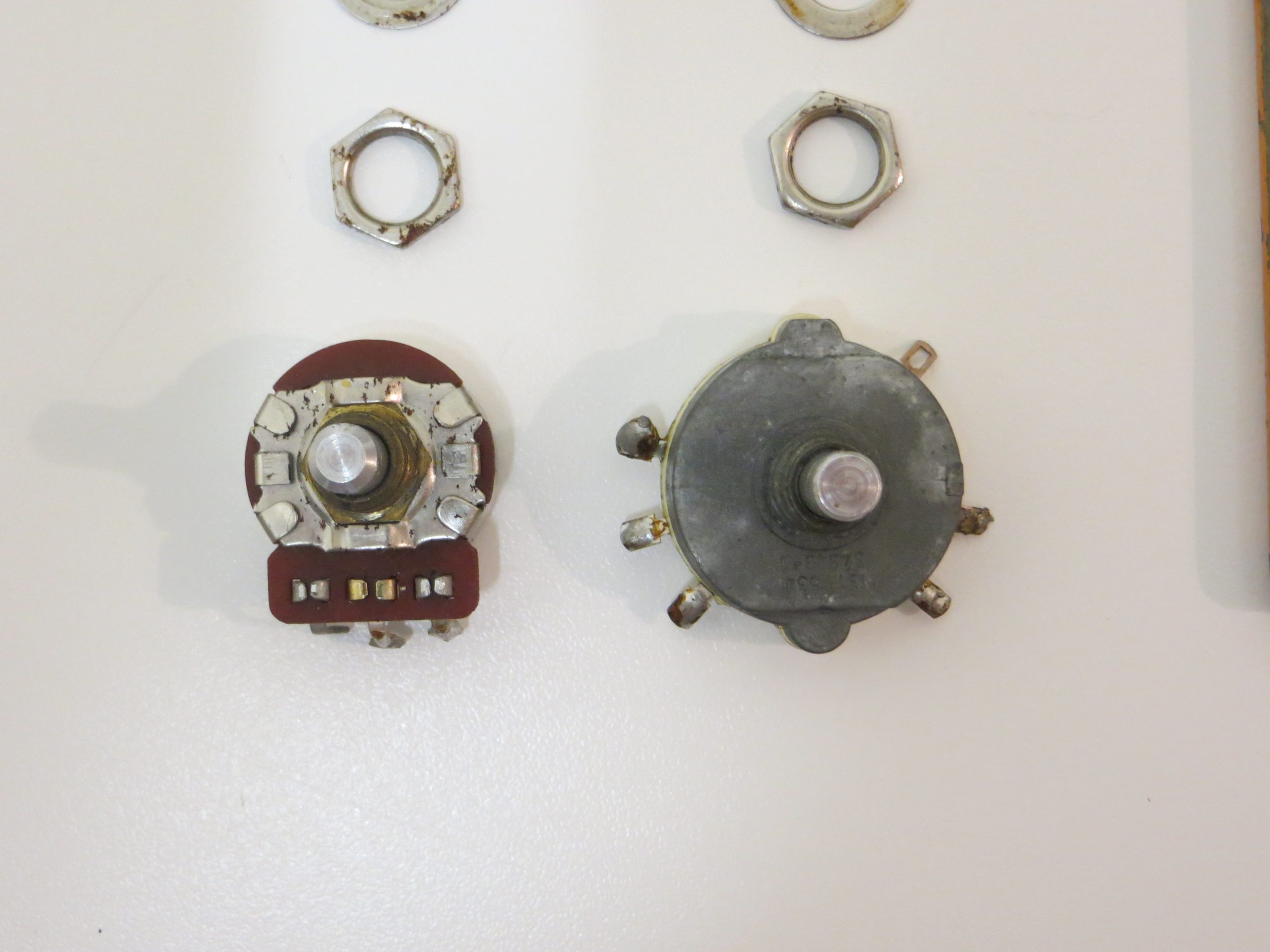
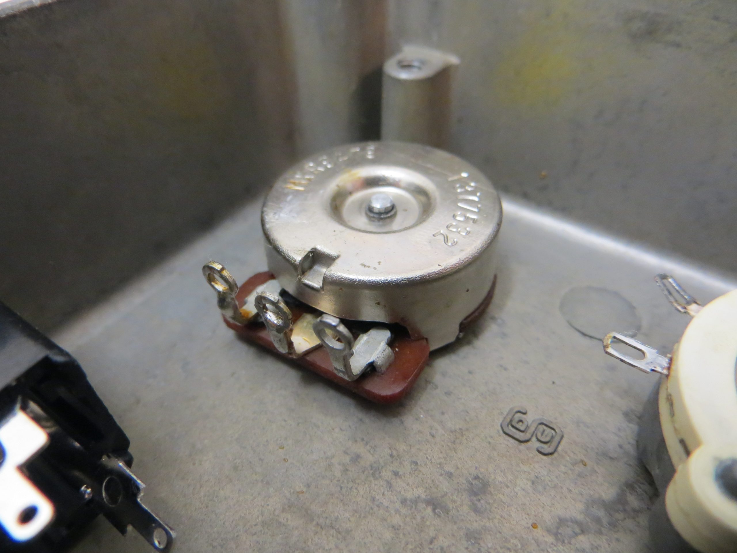
- 2 x CTS Potentiometers
- 2 x Metal Washers
- 2 x Hex Nuts
- 1 x Grey Metal Washer (Sat on top of Intensity Hex Nut, may not be original)
- 2 x MXR Knobs
- 2 x Rubber Boots (Extra boot for Intensity knob is an addition by me)
- 2 x 1/4″ Stereo External Mount Jack Sockets (Not original)
- Battery Snap
- 1 x Case Screw (3 Missing) (Not original)
- 2 x PCB Screws (2 Missing) (Not original)
- 2 x PCB Mount Grommets (2 Missing)
Parts Needed
- 1 x Enclosed Mono 1/4″ Jack Output Socket (Switchcraft – 111X)
- 1 x Enclosed Stereo 1/4″ Jack Input Socket (Switchcraft – 112BX)
- 1 x Carling DPDT Switch with solder lugs (Carling Technologies – 316-B-PP)
- 1 x 2.1mm DC Socket (Cliff UK – FC681473)
- 8 x Philips Pan Head Machine Screws (4 for Enclosure / 4 for PCB)
- 4 x Rubber 3mm Grommets (Davies Molding, LLC – 5104)
- 5mm Closed Cell Foam
- Stranded wire
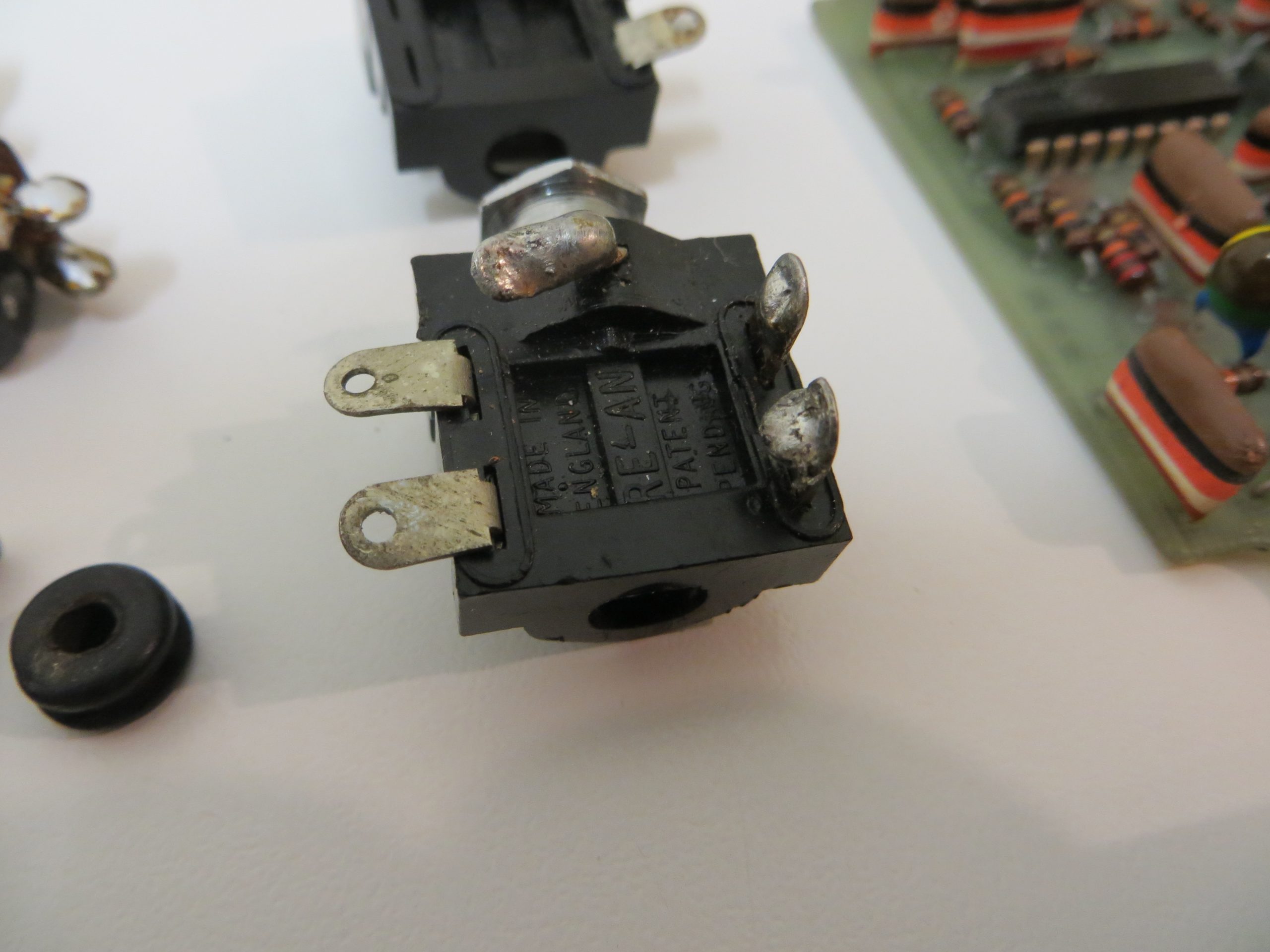
You can see that I have the original jack sockets that were removed from the pedal by the repair technician. These were not the original sockets so the pedal must have been repaired previously. I suspect in the 70s because the sockets are Made in England Re-An sockets. Definitely not original because MXR pedals all came with closed type Switchcraft sockets.
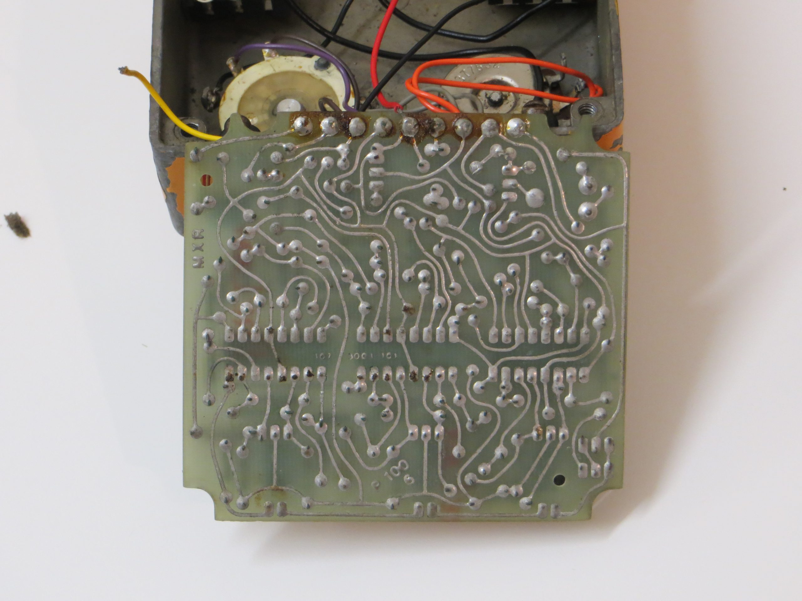
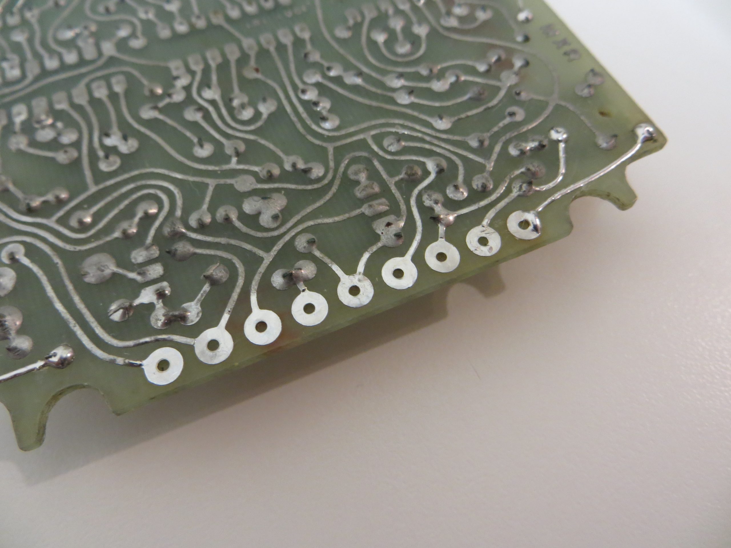
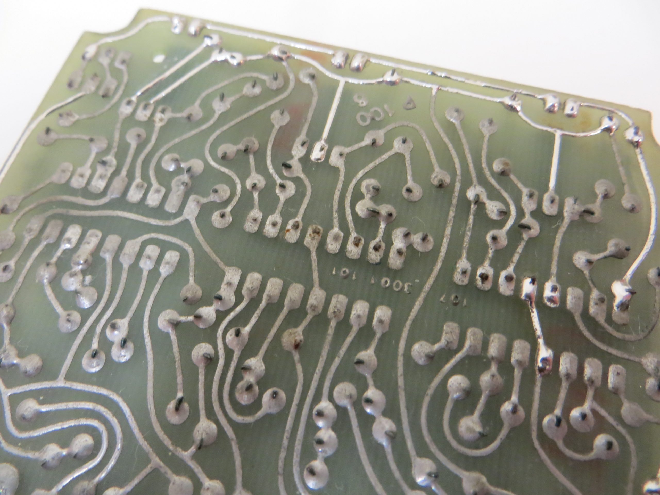
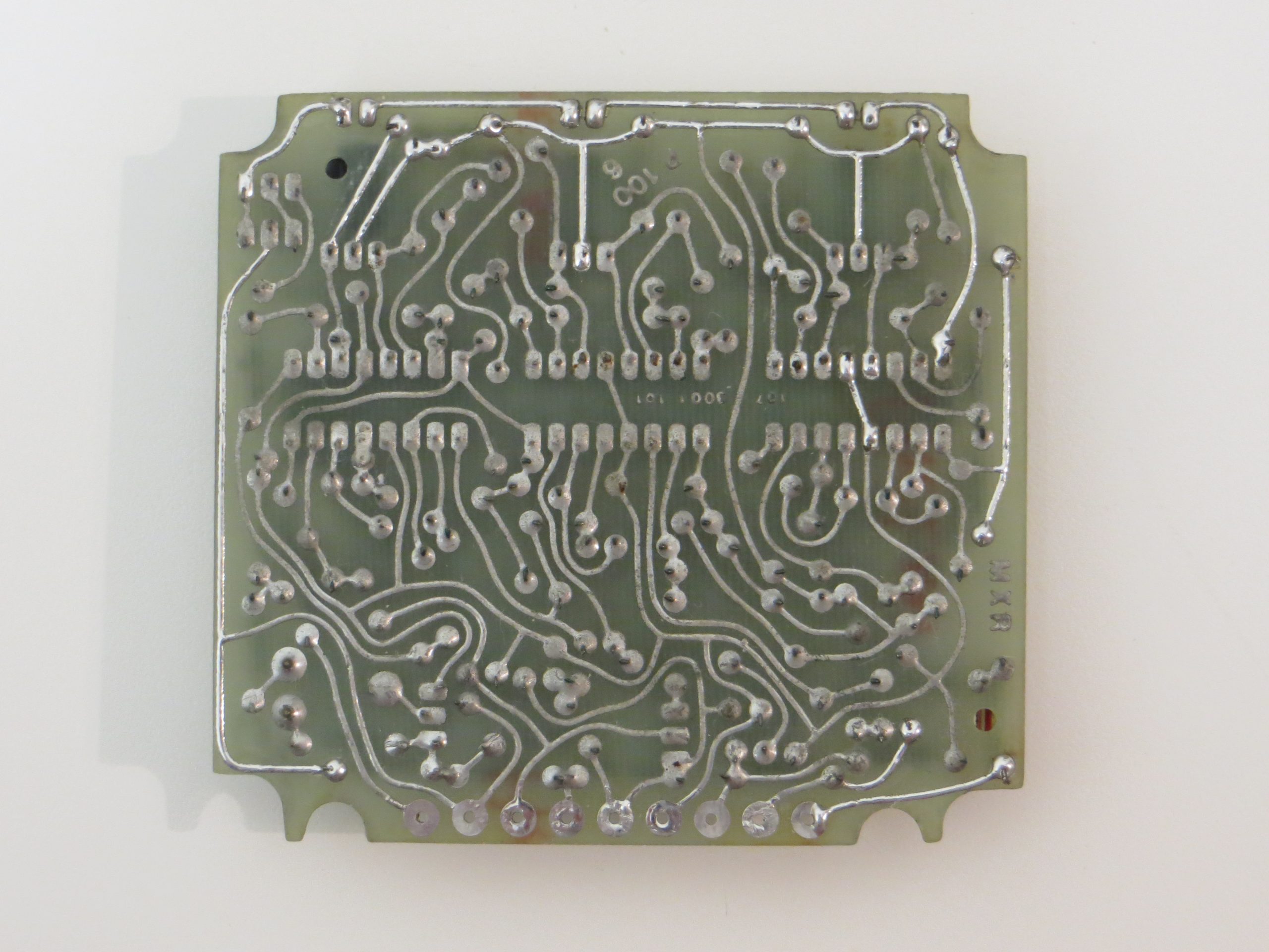
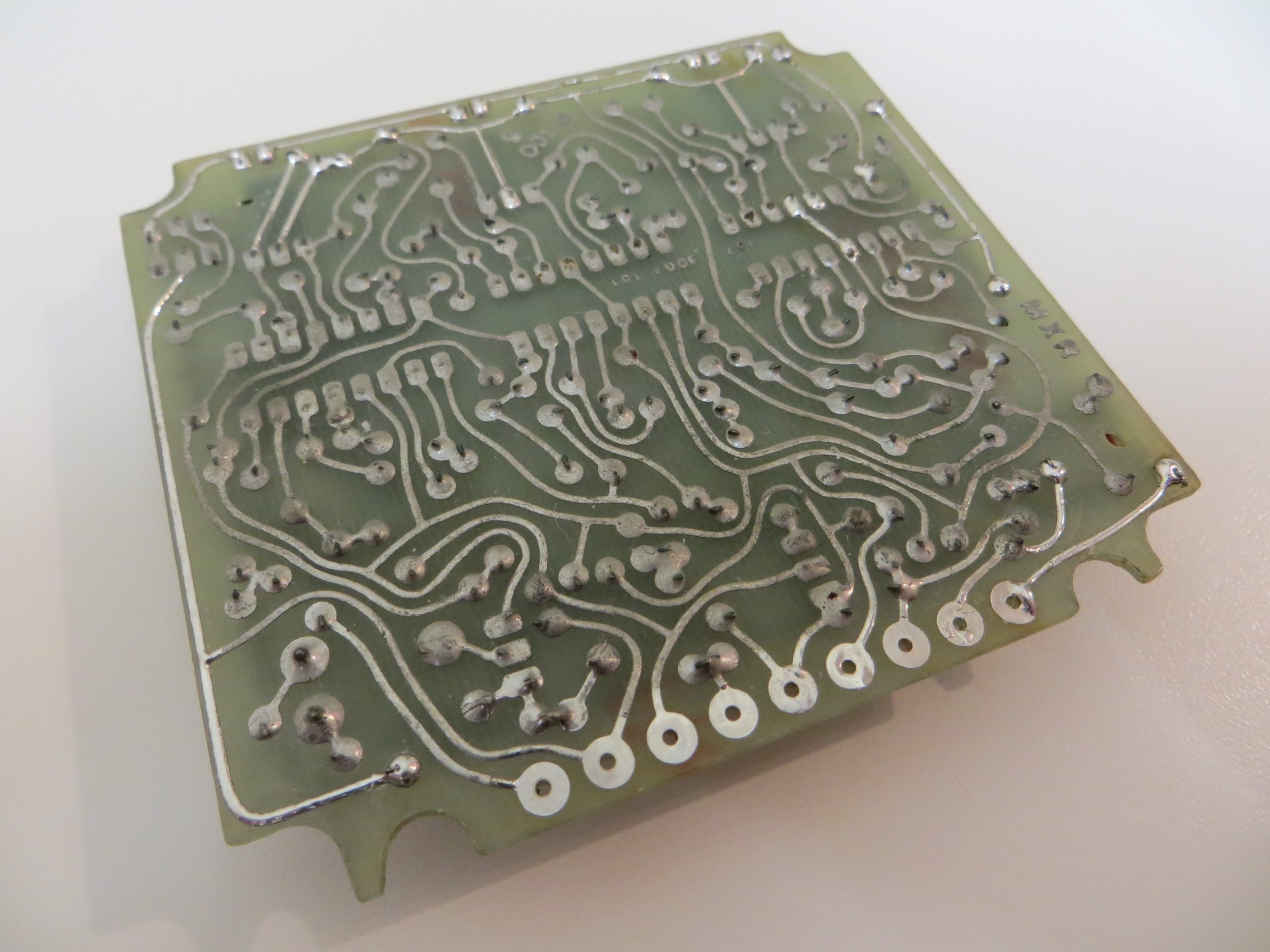
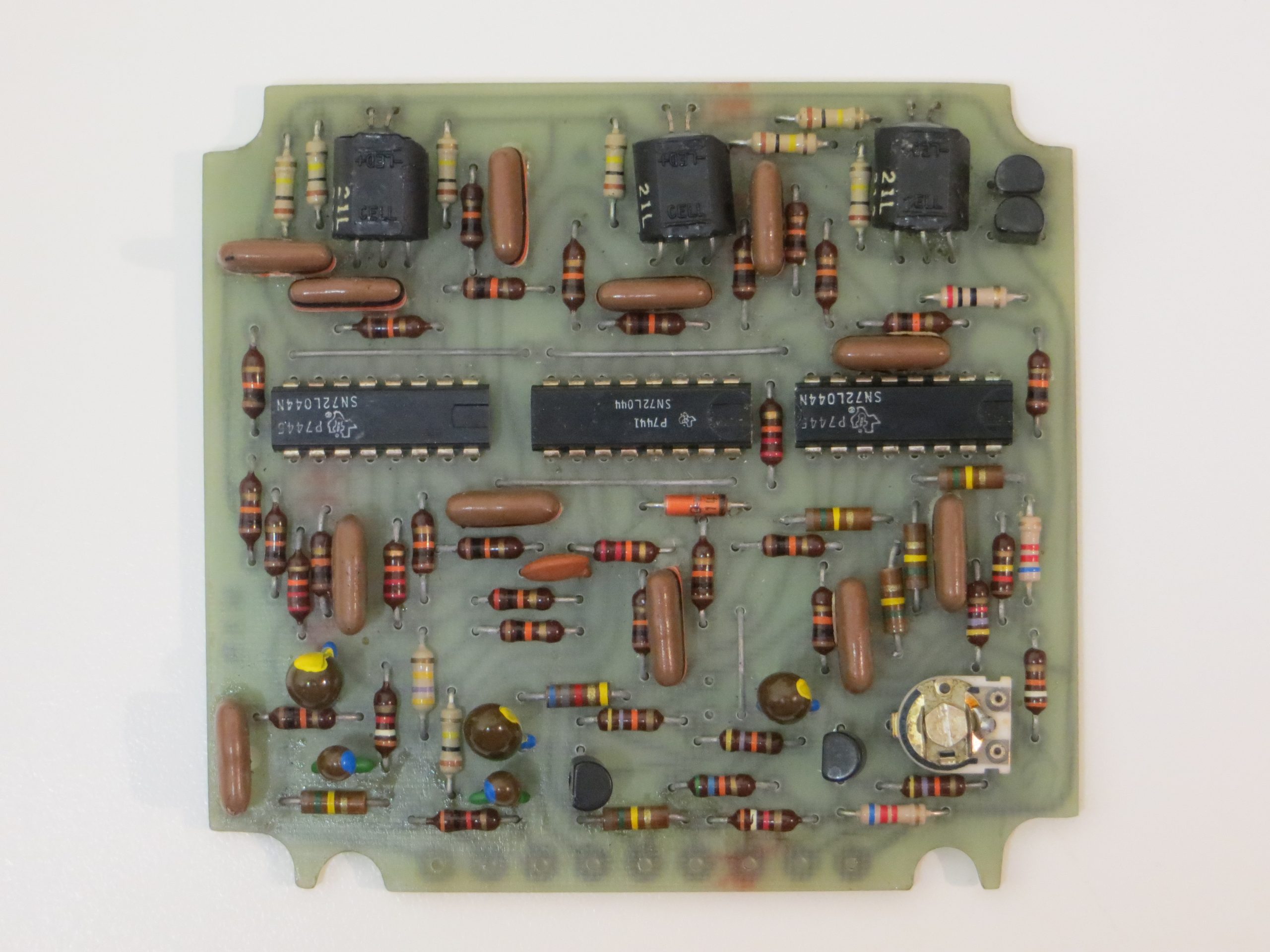
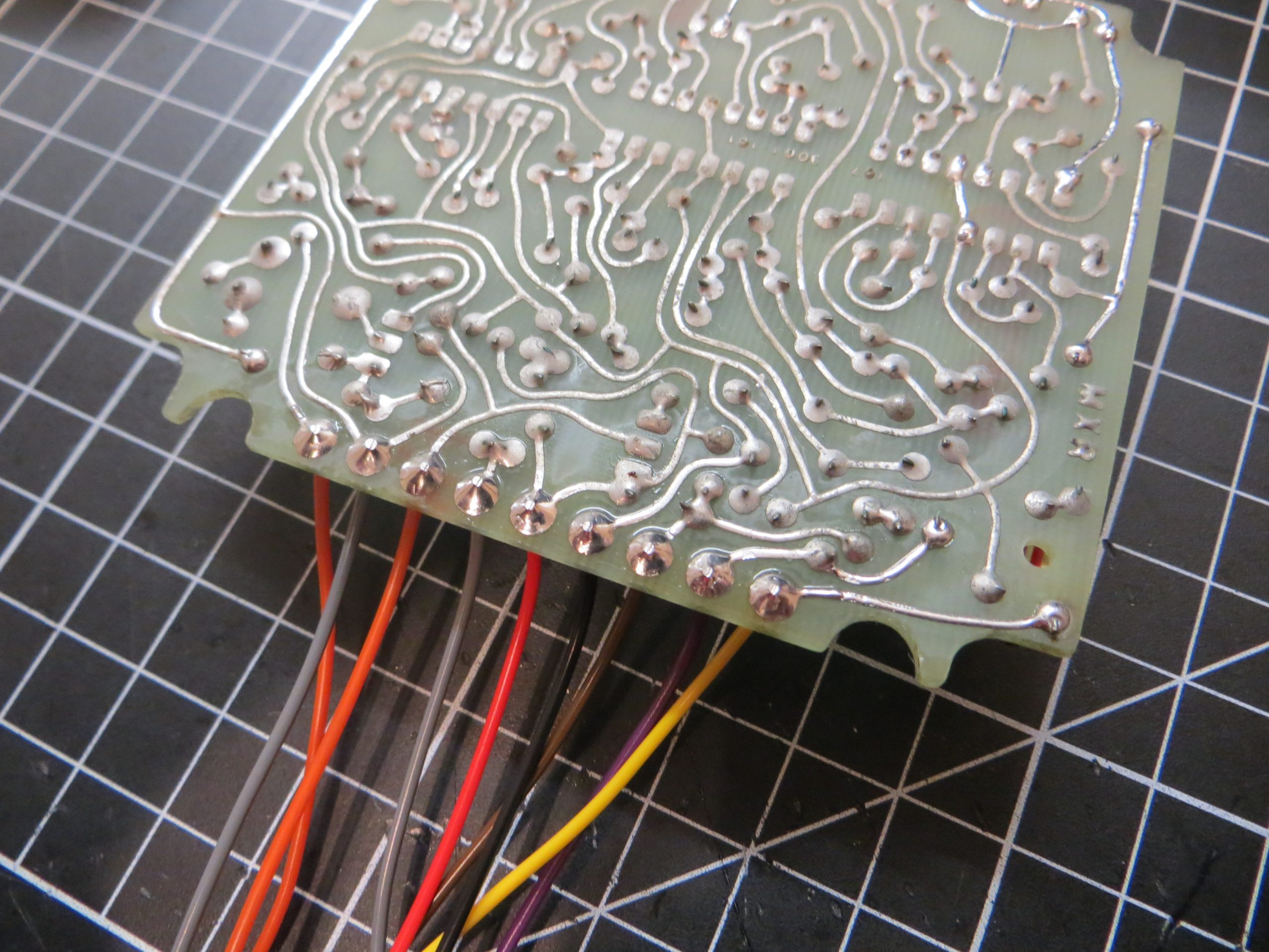
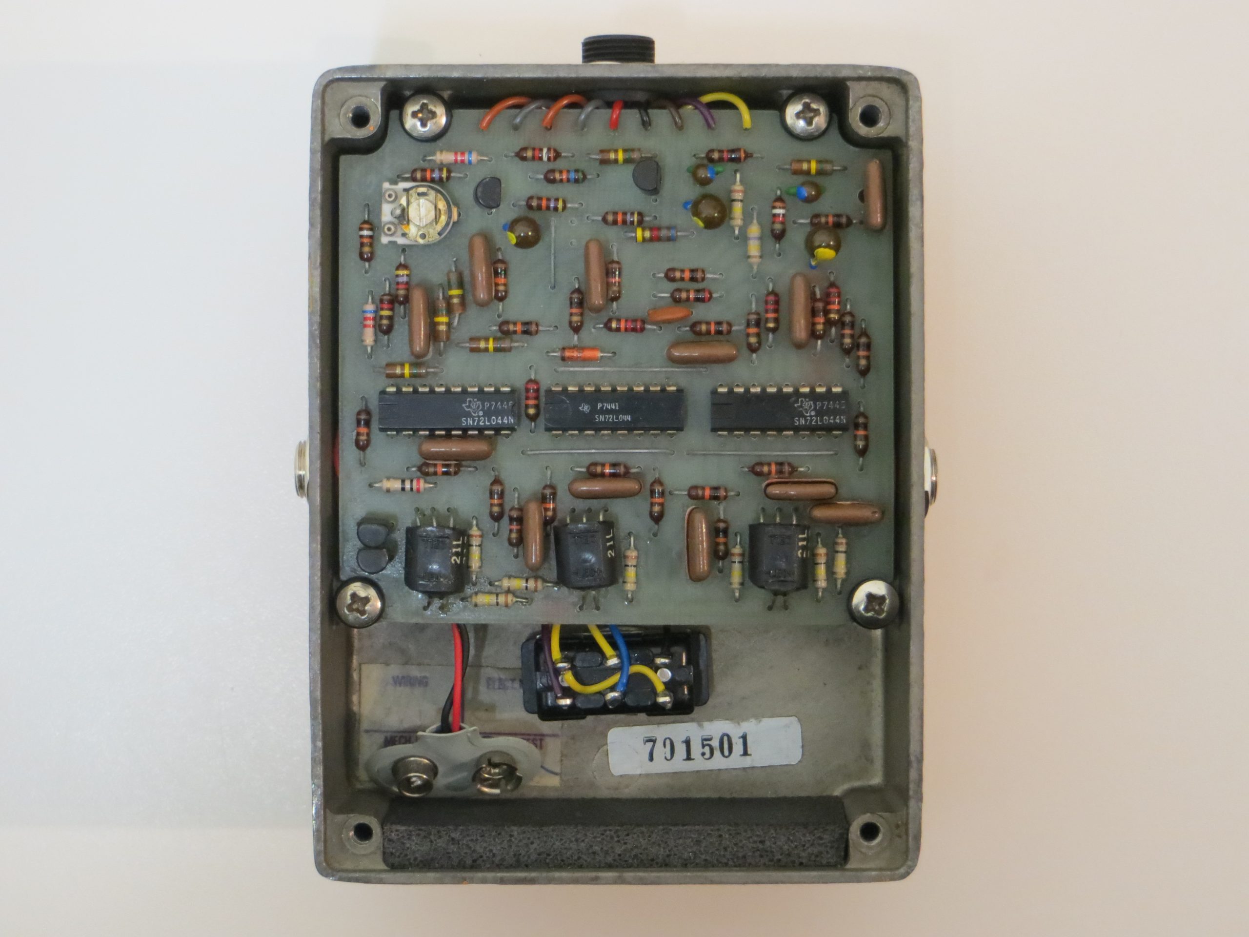
The PCB was cleaned of flux and other mess with 99.9% IPA. I carefully removed the wires so as not to lift or destroy any of the PCB traces. This is a single sided PCB so it is very easy to destroy the wire holes when removing the wires. I cleaned up the wire holes using desoldering braid. Notice how there are no lifted, or broken traces and the area is clean from grime.
The PCB traces are badly tarnished which was probably caused by poor storage in a damp location by a previous owner. I went over some of the badly tarnished traces with fresh solder. I could have probably done the entire PCB but I wanted to avoid putting any stress onto the components. I think this is enough to prevent any further degradation to the PCB if it is stored correctly in the future.
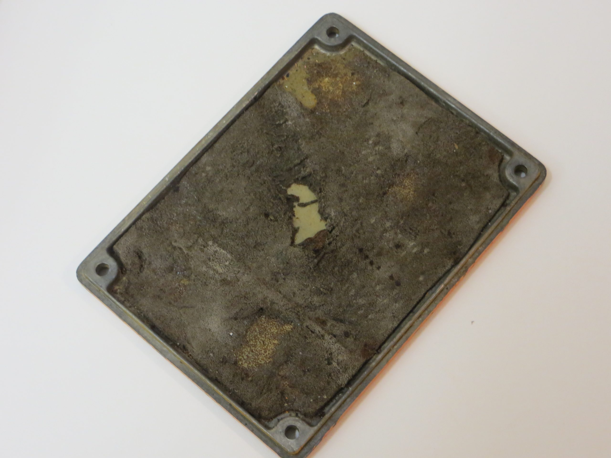
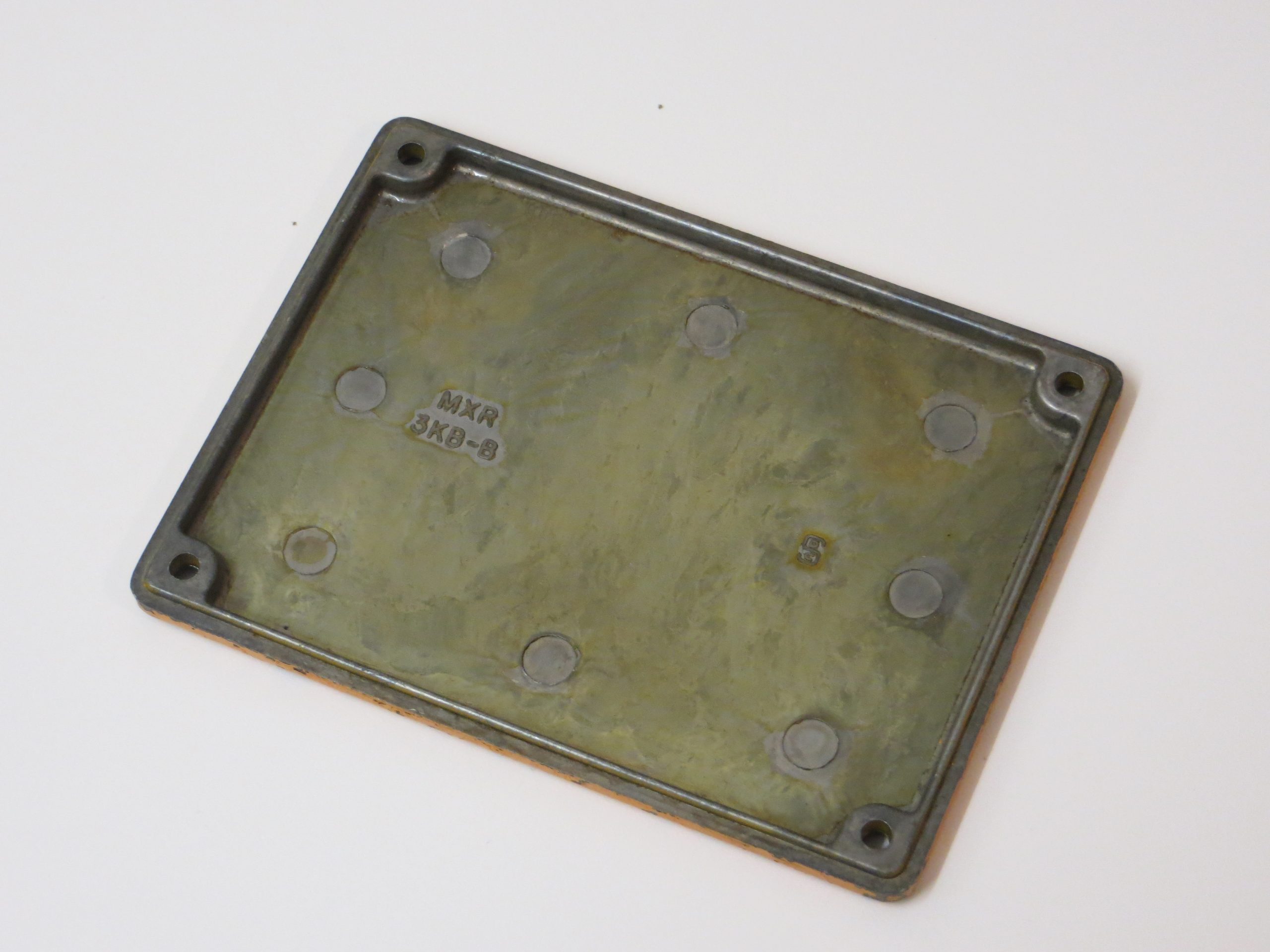
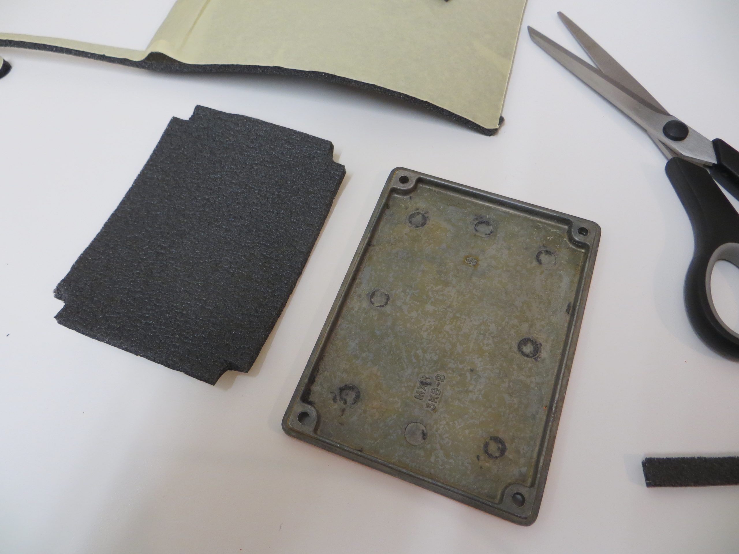
I then cleaned up the disintegrating open cell foam and added some nice new closed cell foam. Closed cell foam is denser than open cell so needed to be thinner than the original foam to not put too much pressure onto the components. Original foam is around 7mm so I went with 5mm. Pressing the enclosure back plate down onto the foam will leave a slight imprint that can then be used to help cut out the correct shape.
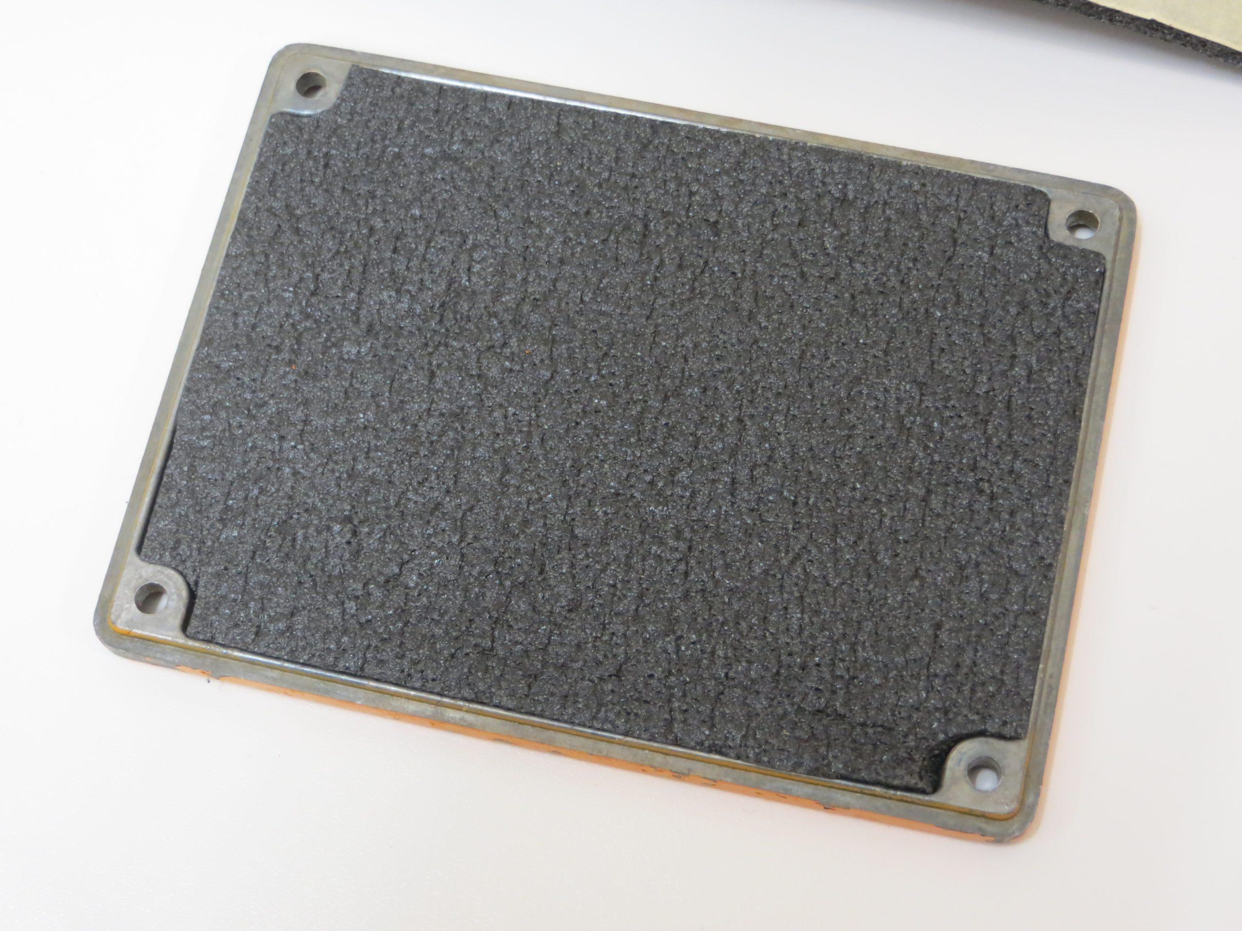
The results look great. I also replaced the battery foam in the main enclosure. This new foam should last a lot longer than the original stuff.
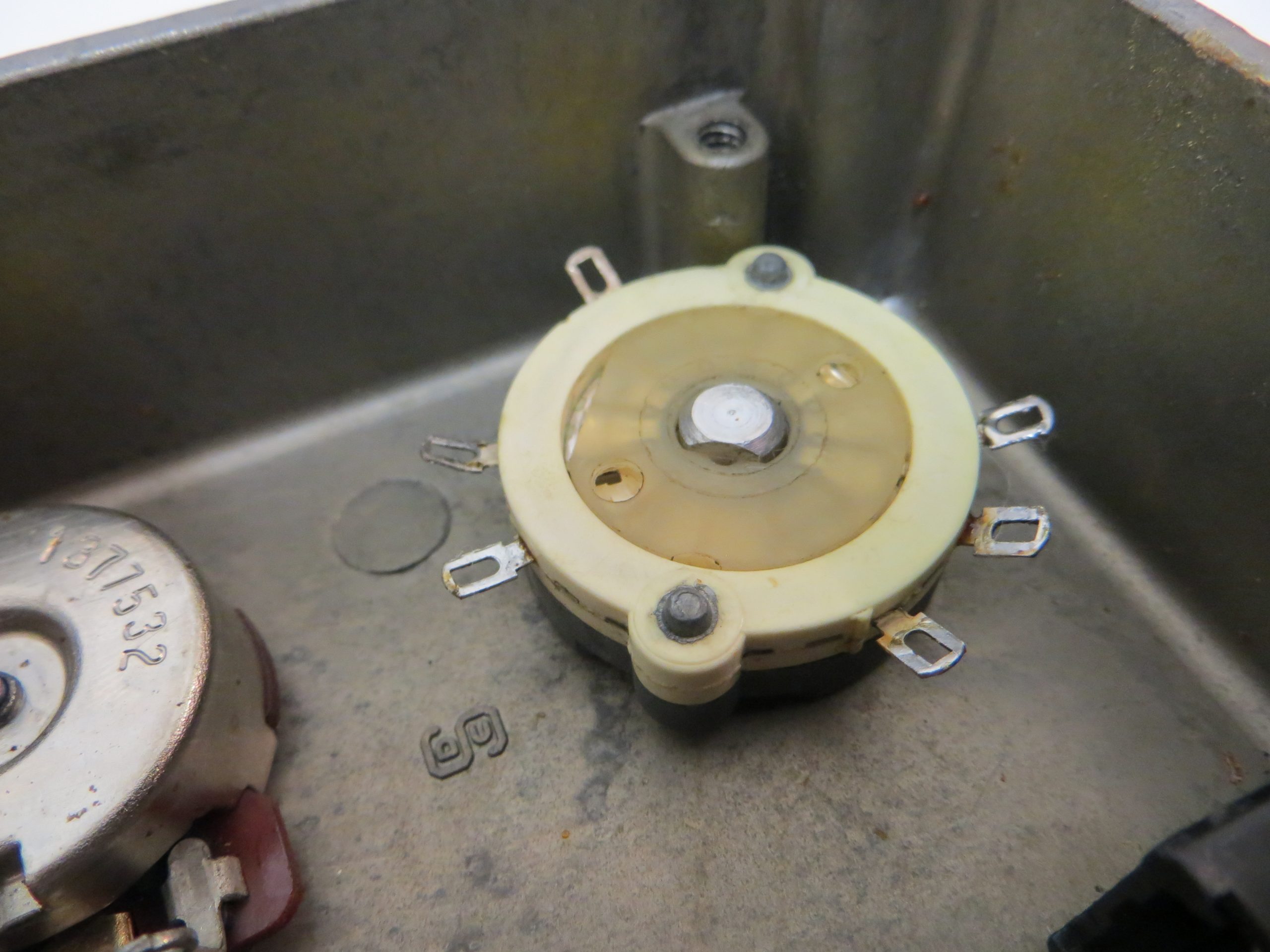
The next stage was to add the components back into the enclosure. The original CTS pots along with a new Carling switch for true bypass, two new Switchcraft 1/4″ jack sockets, and a Cliff DC socket.
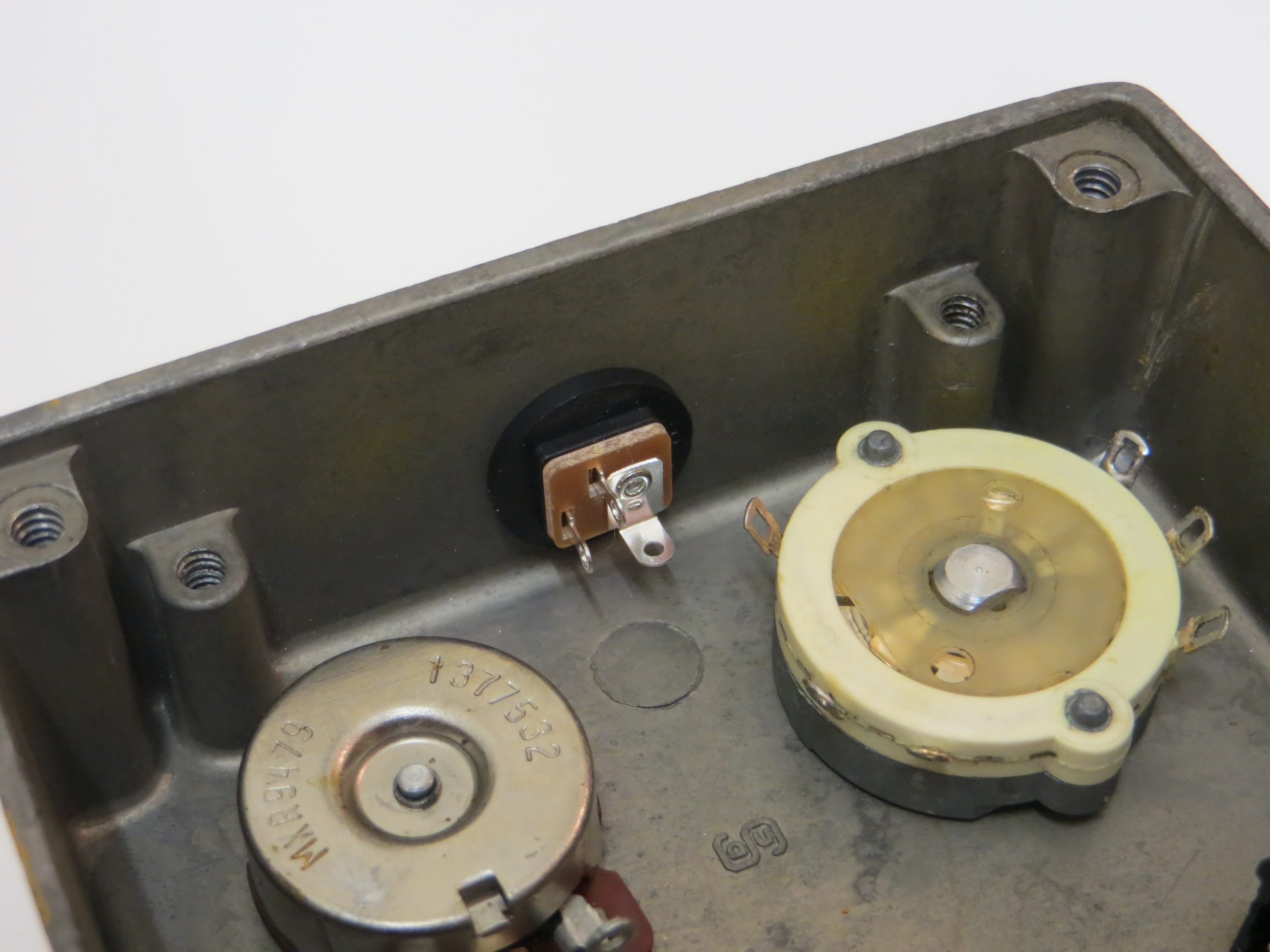
I drilled a hole into the enclosure for the DC socket. I chose to add this socket to the top of the enclosure as is standard on a lot of pedals. I know that MXR did add DC sockets to some later pedals and this was on the left side above the input jack. This would impede on right angle jack sockets so is not a great idea on this particular pedal as the real benefit to adding a DC socket is to allow easy integration onto pedal boards. So I am happy with my choice of location. The difficulty was getting the hole as close to the top of the pedal as possible.
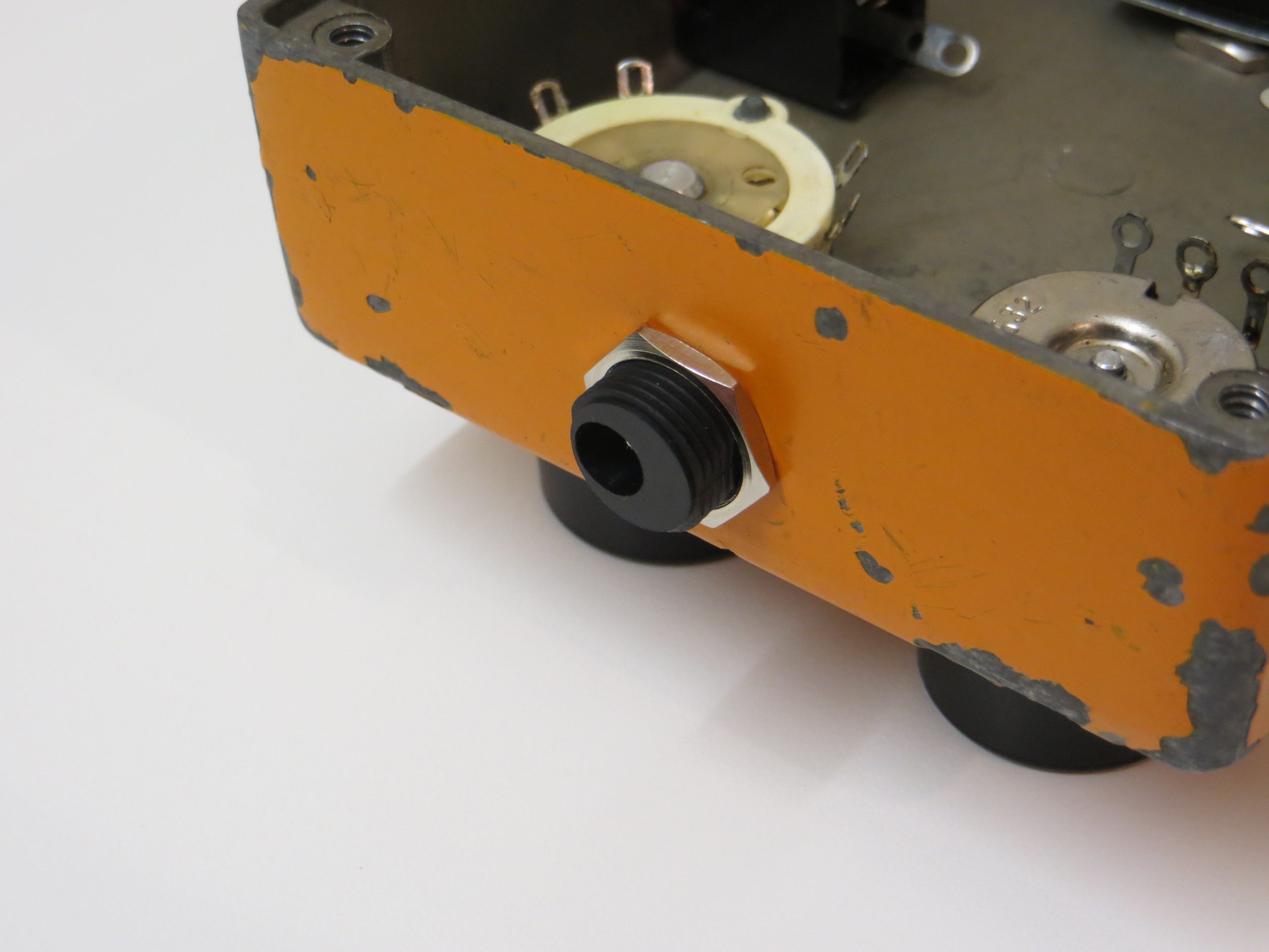
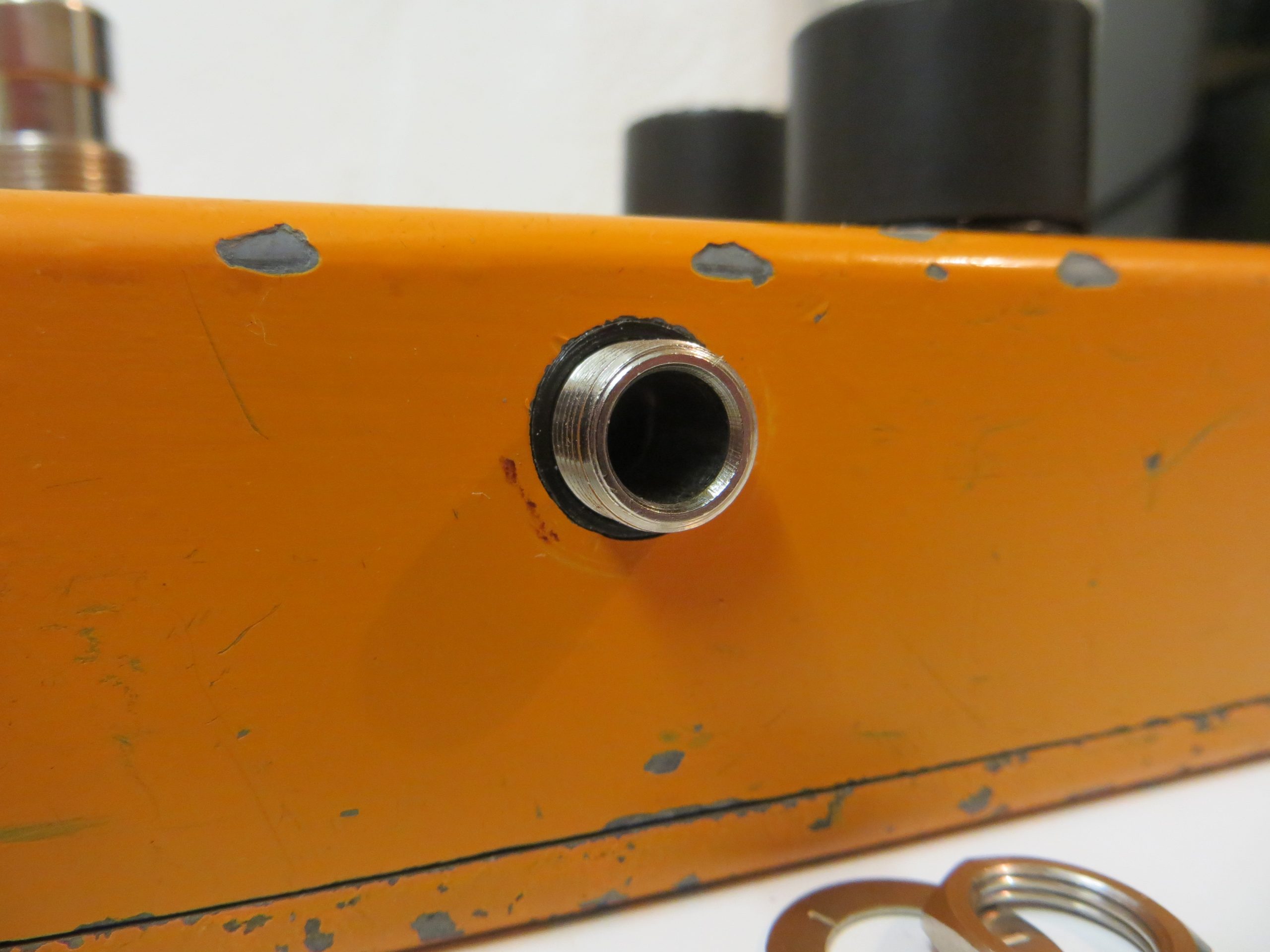
There was one serious problem I had to overcome when installing the new jack sockets into the enclosure. When I had the pedal modded in 2000 the repair tech used jack sockets with a none standard mounting diameter. In order to fit the sockets the repair tech reamed out the original holes to make them larger. Rather than get an appropriate jack socket to the correct size, he took the backwards decision to permanently alter a vintage pedal enclosure making any future restoration very difficult. This now means that my new Switchcraft sockets do not fit into the extra large holes.
I solved this by creating some plastic ferrules by cutting the ends of the old jack sockets off and threading them over the new ones. Not happy about this but it allows the new sockets to fit the holes now. Two washers were also needed on the inside of the sockets to stabilise them and allow them to sit flush.
The 1/4″ jack and DC sockets were mounted so the ground solder lugs are closest to the enclosure walls. This will allow neater wiring for the grounding scheme. The Carling switch was installed using the original knurled washer to keep the original aesthetics of the MXR pedal. The Cliff DC socket does protrude quite far out from the pedal. This is necessary though in order to allow the PCB to sit in the correct place. I much prefer this internal mounted Cliff DC socket over the standard externally mounted one all pedal modders seem to use. Using an outside mounted socket would not allow the whole assembly to be removed without desoldering. This is not the MXR way.
Wiring Scheme
The next process was to work out the wiring scheme. I want to use as many best practices as possible.
True Bypass Switch with Input Grounding
This will ensure the pure guitar signal is going direct from the input to the output jack when the pedal is disengaged.
Input Jack Battery Disable
This prolongs battery life by taking the battery out of circuit when the input jack is removed. It uses the ring of the stereo input jack to connect the battery ground into circuit. Removing the jack removes the ring ground connection.
DC Jack Battery Disable
This will again prolong the battery by taking it out of circuit when the DC socket is used. Plugging something into the DC socket breaks the battery’s positive connection.
(Schematics and wiring diagrams coming soon.)
Wiring the Pedal
I looked at the original MXR wire used and tried get a wire as close to it as possible. The wire I used is a little more rigid but this should help prevent breaking a little better than the original wire.
I matched the wire colours up with the ones I removed as most were original. Only the FX output wire had an incorrect colour because this had been replaced for some reason. I could not find a single photo of this board revision anywhere online to confirm the correct colour so I chose purple for this wire. I later found out that this wire should be white so I might replace it at a later date.
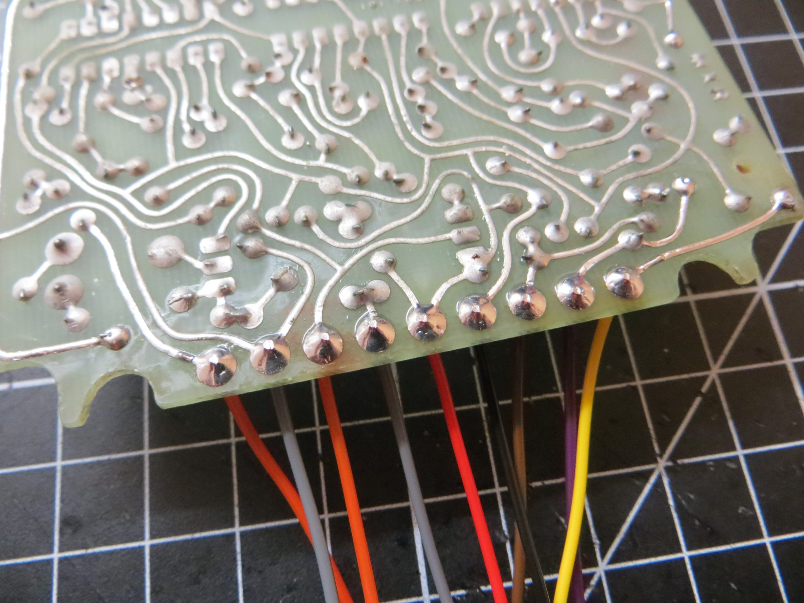
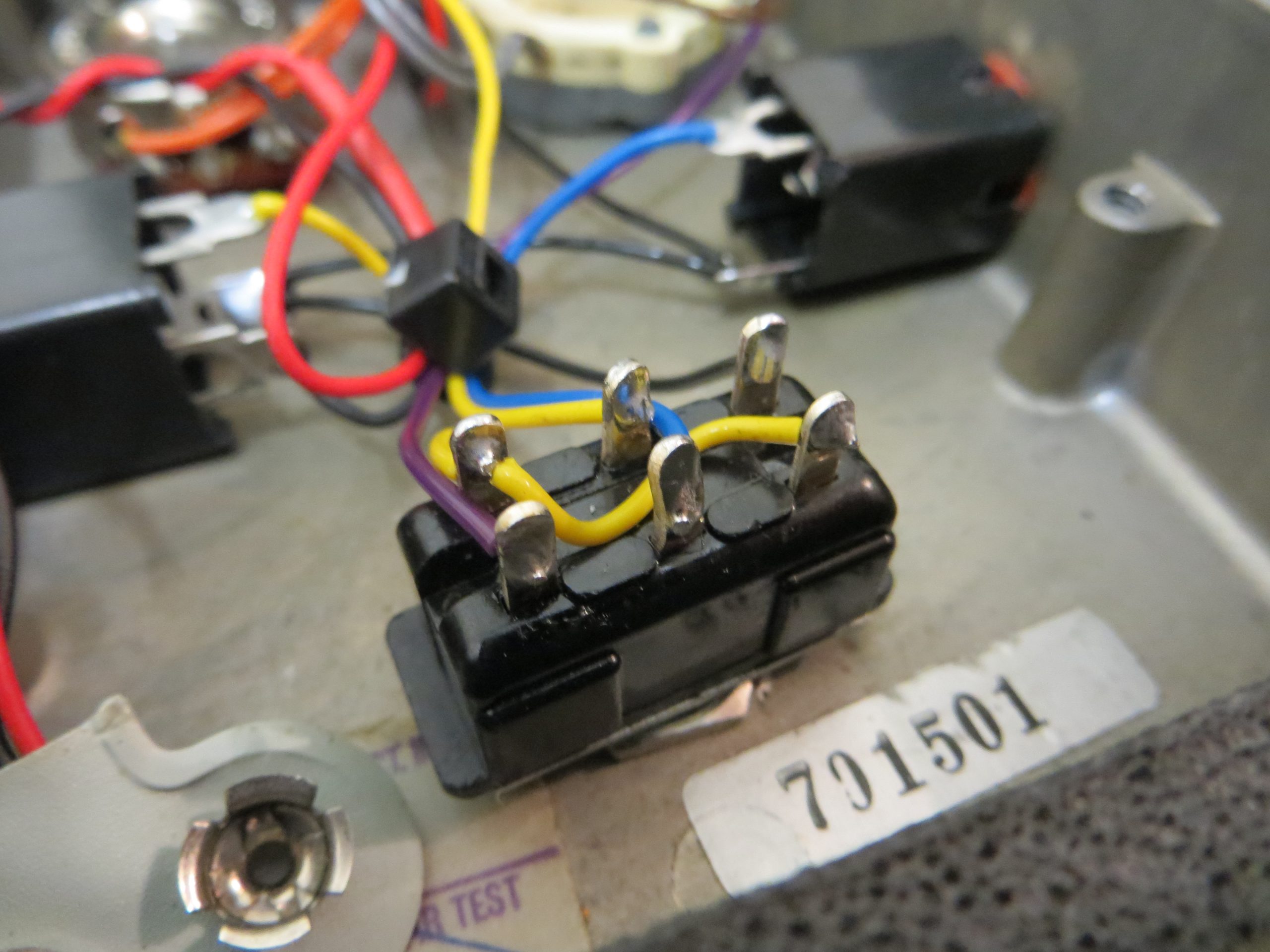
I start by adding all the static wires into the enclosure. None of these go to the PCB. I started with the grounding wires (Black). DC socket center to output jack sleeve, output jack sleeve to input jack sleeve, input jack sleeve to switch. I next added the battery snap. I chose to reuse the original battery snap as it was still in good condition. I had bought a modern plastic replacement but decided to keep the pedal as authentic as possible. Battery snap ground wire (Black) to the stereo input jack ring and the positive wire (Red) to the DC socket switch output. Next I added the guitar input (Yellow) and guitar output (Blue) wires between the switch and jack socket tips, as well as the true bypass link wire on the switch (Yellow). The last static wire I added was for the FX output between the switch and the Intensity potentiometer (Purple, but meant to be white).
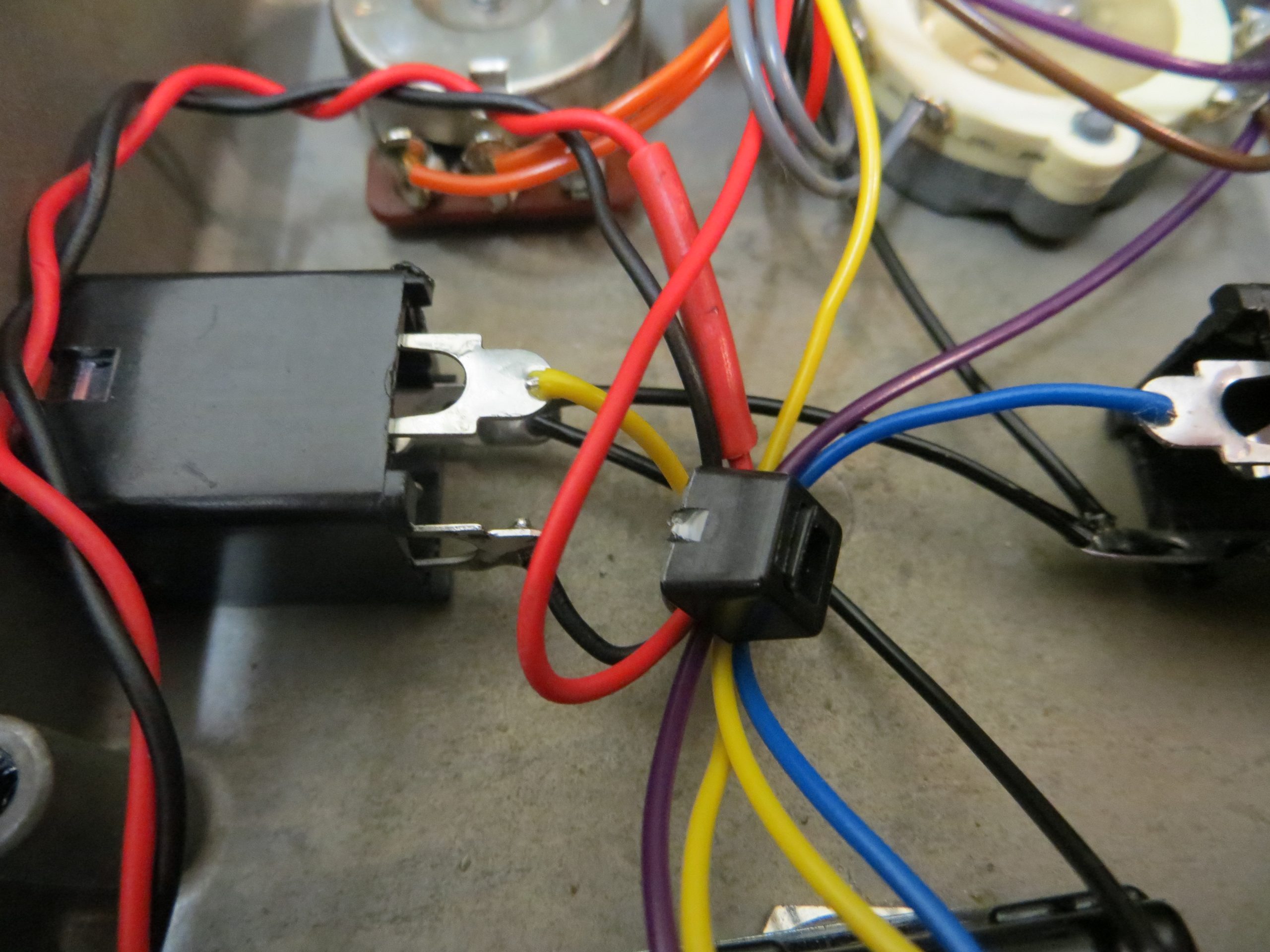
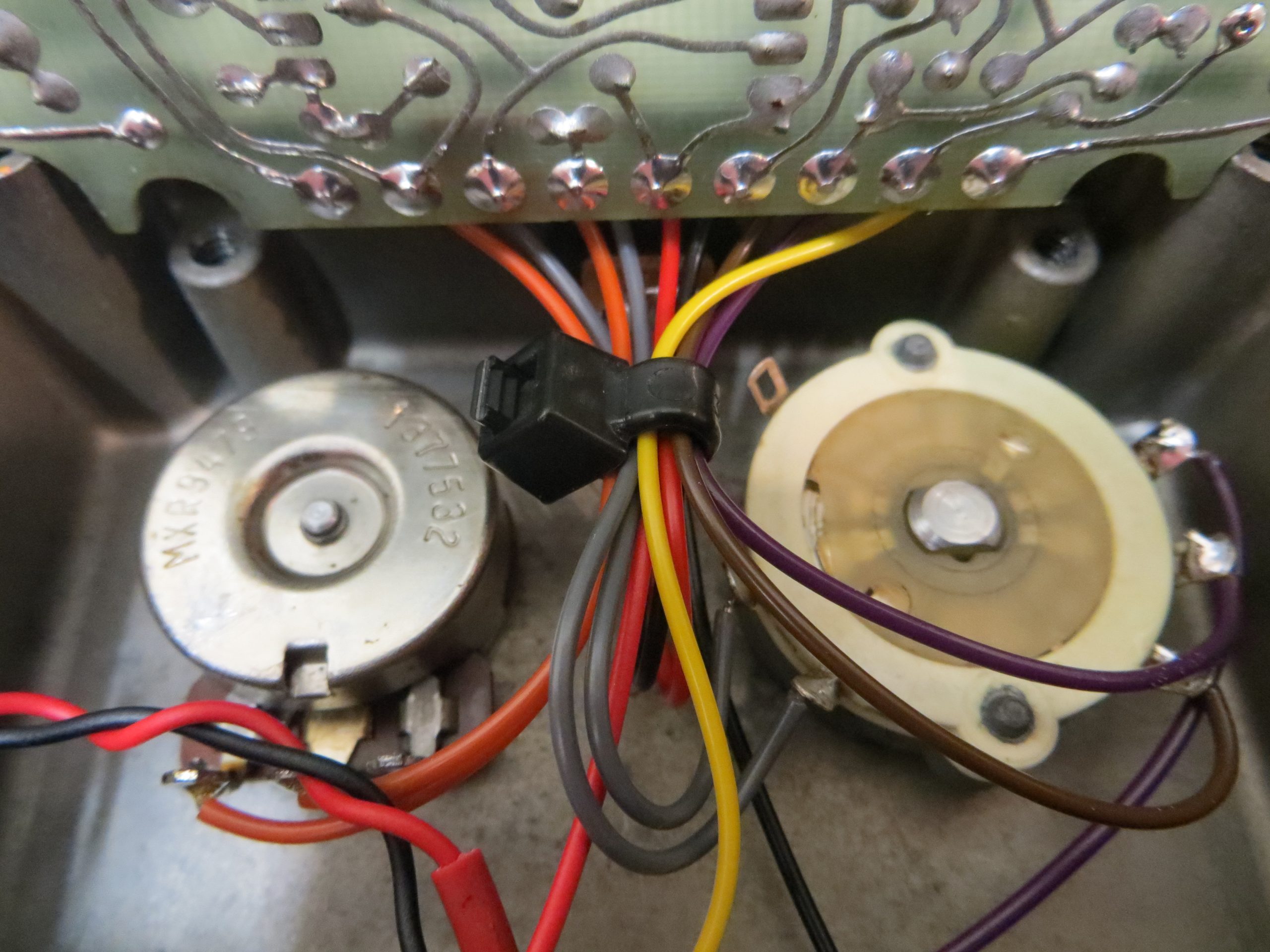
Now onto the PCB. The PCB will solder to the Switch for the FX input (Yellow), the DC socket for the ground (Black) and power (Red), and then the other wires all go to the potentiometers (Orange, Grey and Brown). I added the wires to the PCB and kept them longer than needed. It was then just a case of holding the PCB close to the enclosure whilst shortening the wires and soldering them in one by one.
Once all the wires were soldered I added two plastic cable ties to keep the wires neat and prevent any movement that could stress the wire connections and cause a break. This is especially important for the battery snap which I looped in such a way that no movement will ever be transferred to the connection. Job done.
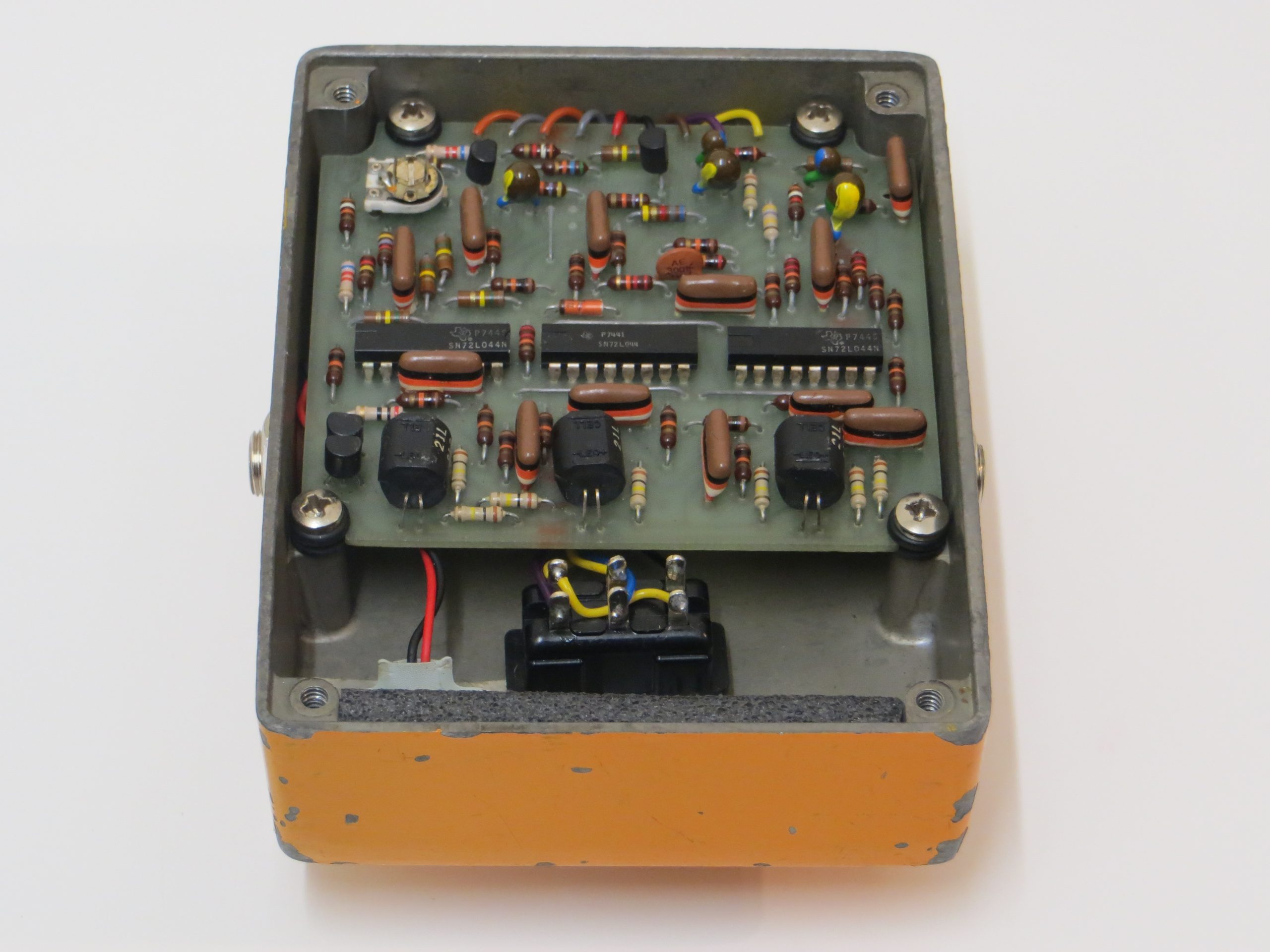
Final Results
Pedal is back to fully working order and fully modded for a modern pedal board and power requirements. I am very happy with the results.
Before and After Comparisons
Slide the image handles to see before and after images.
I hope you enjoyed reading about my MXR Phase 100 restoration. It is the fist post of many to come.
Thanks for reading.
I will be offering this modification service in the not too distant future. Online shop coming soon.
It is alive.
Thank you so so much for this, I was able to figure out how to replace my newer MXR with the older SPDT Carling Footswitch in it, over to Dunlops new ECB switch! This helped me a ton 🙂